• The move to the new server is done. There are some software and database maintenance updates in process. This has us passing the hat around to help out. We appreciate any donations. Seriously, even a dollar helps. The payment page may be found here - https://www.audiokarma.org/support.html

Nikko gamma 30 Tuner

Jon Q

New Member
Hi

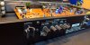
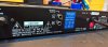
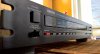
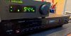
I bought a Nikko gamma 30 tuner in excellent condition. I want to do a restore and a circuit upgrade.
I need the schematic diagram and I think it's on the last page of the instruction manual. Later I can post here my first thread thread (Nikko tuner gamma 30 upgrade)

Someone can help me? Thank you for your attention.
Atentamente/Best Regards

Jon
 
Register to hide this ad
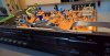
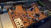
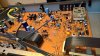
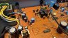
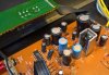
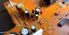
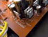
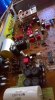
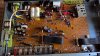
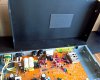
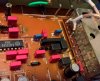
Show a few pics of the inside details so one can see what chips they used. From there you can go to the device datasheets and get an idea of how they designed it, compare against other models that there are schematics for.
 
Show a few pics of the inside details so one can see what chips they used. From there you can go to the device datasheets and get an idea of how they designed it, compare against other models that there are schematics for.

The question is, this tuner is to be included in my system, a first hearing I noticed that it has potential for better performance.
Therefore, what I want is replacement of capacitors, resistors, alteration of some circuits, elimination/deactivation of the AM circuit, placement of new connectors.
It is possible without the manual, but I will lose many hours. With the diagram is much easier and very little time is lost.
 

Attachments

  • 1.jpg
    1.jpg
    68.2 KB · Views: 62
  • 2.jpg
    2.jpg
    105.2 KB · Views: 59
  • 3.jpg
    3.jpg
    99.7 KB · Views: 58
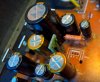
I can only make out the Sanyo LA1235 using a double tuned quad coil as your detector, looks like only 2 ceramic filters and a IF amp, could be a LA1222.
These are very good parts for mid performing tuner.
When taking pics, take them right above the area of interest, zoom in, one area at a time, so one can clearly read the tops of the chips, not at the angles as you have done, since they lose definition.
I have no idea what stereo decode they used but it looks to be a NEC branded part.
I really do not know how you can determine it has potential for better performance, in what capacity as far as performance &/or sound quality?
If you have little knowledge on how it works, we do not have a schematic, all the parts they used, how can one determine ways to improve it?
To be honest, I do not think there is a whole lot to be gained. You will lose hours with minimal or no gain or damage in which you are unable to repair. Sometimes it is best to be happy with what you have.
BTW the AM circuits are probably powered down for FM op anyways, so removing them does nothing.
 
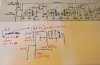
I forwarded a hi-res copy of the schematic to Jon.
Here’s a fuzzy copy for others to review.
I’m looking forward to see his mods.

upload_2019-11-20_19-1-8.jpeg
 
Hi "rcs16"
I apologize for the late reply, but I finally managed a little time available.

I really do not know how you can determine it has potential for better performance, in what capacity as far as performance &/or sound quality?
If you have little knowledge on how it works, we do not have a schematic, all the parts they used, how can one determine ways to improve it?.

Yes it is possible to have better performance and in the sound quality. Now that I have the manual/diagram, kindly provided by w1jim (thanks again). The upgrade is very easy to do.
Another situation, the choosing many of the upgrade is personal. The reason... this tuner is meant for my personal system.
 
All resistors of NIKKO gamma 30, were replaced by Vishay , RN55E 0.1% - 25ppm and RN55C, 1% 50 ppm. In critical situation (audio signal and "de-emphasis 75us" ) is replaced by RC55Y series of welwyn (0.1% - 15ppm).
Other resistors have been replaced by Philips 1% 50ppm resistors.

The ceramic capacitors have been replaced by polypropylene of WIMA (except, front end). At critical points (IF) the 1837 series of vishay is used.
The oscilator MPX and de-emphasis equalization have been replaced the mica capacitors of cornell dubilier.

About electrolytic capacitors. From several models that were tested , I opted for the Nichicon, KM and UFG series. (M) for its sound performance.

The three power supplies have been changed for better performance. The regulation,12.8V is used a different topology than the original circuit. Now, uses a mosfet BUZ80 of siemens and low noise reference zener, TLP431B (0.5%) see pic. 6, 7, 8, and 9. The 5V and (27V / FM tuning), were optimized. (pic. 10,11).

All rectifier diodes have been replaced by RHRP860 hiper fast diodes of ON, (pic. 12). The result is surprising. Personally for audio, I'm not a fan of Schottky diodes.
The stand-by switch, has been removed, now is mains power SW. The reason is, less power loss, less noise and better performance.
 

Attachments

  • 03_.jpg
    03_.jpg
    90.3 KB · Views: 38
  • 04.jpg
    04.jpg
    83 KB · Views: 37
  • 05.jpg
    05.jpg
    56.2 KB · Views: 35
  • 06.jpg
    06.jpg
    47.2 KB · Views: 35
  • 07.jpg
    07.jpg
    82 KB · Views: 35
  • 08.jpg
    08.jpg
    78.7 KB · Views: 34
  • 09.jpg
    09.jpg
    71.2 KB · Views: 35
  • 10.jpg
    10.jpg
    66 KB · Views: 36
  • 11.jpg
    11.jpg
    78.3 KB · Views: 36
  • 12.jpg
    12.jpg
    84.7 KB · Views: 37
Last edited:
To see its performance (NIKKO gamma 30) with other types power cords, the original has been removed. With the help of a CNC, a simple change to the rear panel, I can add an IEC connector and new Neutrik (NC3MD-L-B-1) plugs.
The choice of this type of plug is only due to using xrl cables in my personal system.

cheers

to be continued
 

Attachments

  • 16.jpg
    16.jpg
    58.5 KB · Views: 33
  • 17.jpg
    17.jpg
    58.6 KB · Views: 32
  • 18.jpg
    18.jpg
    71.6 KB · Views: 31
  • 19.jpg
    19.jpg
    74.9 KB · Views: 32
  • 20.jpg
    20.jpg
    55.7 KB · Views: 32
  • 21.jpg
    21.jpg
    50.9 KB · Views: 33
Last edited:
For a better sensitivity of signal capture, the front-end is also updated, all resistors are replaced by very low noise metal film resistors.
RN55E / C and RC55Y.
The jfet 2SK168 is replaced by BF981 with some changes, see diagram (pic.6). The advantage (BF981), is its low noise and good amplification gain. In the pic. 4, the added components are marked in yellow.
 

Attachments

  • 1.jpg
    1.jpg
    67.9 KB · Views: 30
  • 2.jpg
    2.jpg
    83.3 KB · Views: 30
  • 3.jpg
    3.jpg
    130.4 KB · Views: 30
  • 4.jpg
    4.jpg
    79 KB · Views: 30
  • 5.jpg
    5.jpg
    80.2 KB · Views: 30
  • 6.jpg
    6.jpg
    60.3 KB · Views: 31
3 new pcb boards have been designed, one for main switch with filter, other is a new terminal for the FM antenna, with the F connector and ground terminal. The AM antenna and t AM section was removed.
The third board is for placing the output capacitors of the conrad johnson CJ-D series. Electrolytic capacitors are not used throughout the signal path.

In the master clock (of the microprocessor) the ceramic capacitors were replaced by the mica. (pic. 10)
 

Attachments

  • 7.jpg
    7.jpg
    50.9 KB · Views: 18
  • 8.jpg
    8.jpg
    45.6 KB · Views: 18
  • 9.jpg
    9.jpg
    45.9 KB · Views: 18
  • 10.jpg
    10.jpg
    61.6 KB · Views: 18
  • 11.jpg
    11.jpg
    69 KB · Views: 18
more pictures .... the new components replacing the old ones (pic. 19), some electrolytic capacitors were already leaking.
 

Attachments

  • 12.jpg
    12.jpg
    87.4 KB · Views: 23
  • 14.jpg
    14.jpg
    67.9 KB · Views: 23
  • 15.jpg
    15.jpg
    47.1 KB · Views: 23
  • 17.jpg
    17.jpg
    116 KB · Views: 23
  • 19.jpg
    19.jpg
    93.7 KB · Views: 23
That’s a lot of replaced ceramics!
It would be interesting if you could compare your modded tuner to a stock one.
 
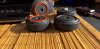
The plastic feet (original) have been replaced by aluminum (alloy 6000) with double insulation. On the top cover (pic 18) is placed (plate, sound coat), this reduces mechanical vibrations and improves the performance of the tuner.
 

Attachments

  • 2A.jpg
    2A.jpg
    69.9 KB · Views: 22
  • 3A.jpg
    3A.jpg
    91 KB · Views: 22
  • 5A.jpg
    5A.jpg
    59.2 KB · Views: 22
  • 7A.jpg
    7A.jpg
    90.2 KB · Views: 21
  • 18.jpg
    18.jpg
    86.9 KB · Views: 21
After all custom made parts have already been assembled, all calibration is made follows.

Once again, many thanks to Mr. "w1jim" for the availability of the schematic diagram, without which I would lose a lot of time.

The reason for this upgrade is very simple and personal. I had a unit like this about 30 years ago, and I can't remember what I did to that tuner.

Now it's time to enjoy ....
I just like... classical music.
 

Attachments

  • 21.jpg
    21.jpg
    67 KB · Views: 29
  • 23.jpg
    23.jpg
    105.4 KB · Views: 29
  • 24.jpg
    24.jpg
    51.7 KB · Views: 27
  • 25.jpg
    25.jpg
    50.5 KB · Views: 29
  • 26.jpg
    26.jpg
    51.7 KB · Views: 29
That’s a lot of replaced ceramics!
It would be interesting if you could compare your modded tuner to a stock one.

Hi "w1jim"
I think that that for next week I will have some tuner units for comparison, Naim, sony ST-J88, audiolab 8000T and possibly a magnum dynalab FT101 etude

later, I will be able to send an opinion and put photos here

jon
 
Amazing work. :bowdown:

what are the sonic results ?

Good question

I had the possibility to make a comparison with 3 tuners, Sony ST-J88, audiolab 8000T and rare naim NAT-01. (I was unable to make a comparative test with the magnum dynalab FT101 Etude).
About the 3 tuners, my preference was NAT-01, that most seduced me.

The first impact, the naim is more musical, the bass is more extensive but a little confusing and also has a greater silence. The NIKKO the bass is not as extensive as the naim, it also had two "defects",
the RF gain was high, sometimes saturated, and d\ont have the same silence as the naim. After several tests, for two weeks, these problems were solved.
The gain of the RF amplifier, (BF981), has been reduced. The IF amplifier, also a small change in signal gain.
An improvement was made to the power supply for IC, LA1235.
The gain of the original circuit (MPX decoder)of nikko gamma 30 is about (4.7X .... 13.44dB), it was changed to 1.41X .... 3dB. The output impedance is now also lower than the original circuit.

This update resulted in a greater silence in the music, more neutral, very fast. The sound is now of the type (recording studio sound).
Finally, to compensate for the limitation of low frequencies (due to the output capacitors of conrad johnson C-JD, having only 1uF). After many tests with various models and manufacturers of electrolytic capacitors and tantalum
A 22uF / 25V tantalum capacitor was added to each channel in parallel with the C-JD capacitors). This combination works very well here. See pic.03

Now I prefer Nikko, he doesn't have the naim musicality, but he has a studio sound, he is more real, more 3D, more neutral and has better bass performance.
During the day the naim is more silence, but at night the nikko performs better.

It was an update that was a little expensive, but with Spectral amplification Pre/Power I am very happy with the final result, especially when is night .....

jon

 

Attachments

  • 01.jpg
    01.jpg
    45.5 KB · Views: 30
  • 02.jpg
    02.jpg
    55.5 KB · Views: 26
  • 03.jpg
    03.jpg
    55.4 KB · Views: 26
  • 04.jpg
    04.jpg
    84.7 KB · Views: 26
  • 05.jpg
    05.jpg
    56.2 KB · Views: 26
Back
Top Bottom