• The move to the new server is done. There are some software and database maintenance updates in process. This has us passing the hat around to help out. We appreciate any donations. Seriously, even a dollar helps. The payment page may be found here - https://www.audiokarma.org/support.html

Nixie tube clock 1950's cold war replica

Teti

Pioneer hoarder
So I've decided to make nice big beefy 1950's replica of Nixie clock inspired by old HP gear. I will use XO for start and later 10Mhz OCXO.

First designing relays for that authentic clicking sound of old gear, 45 relays all together 1 relay for each digit. relays connecting tube cathodes to the ground.

img_20160201_101641-e1463617231319.jpg

img_20160201_101655.jpg

img_20160222_110844.jpg


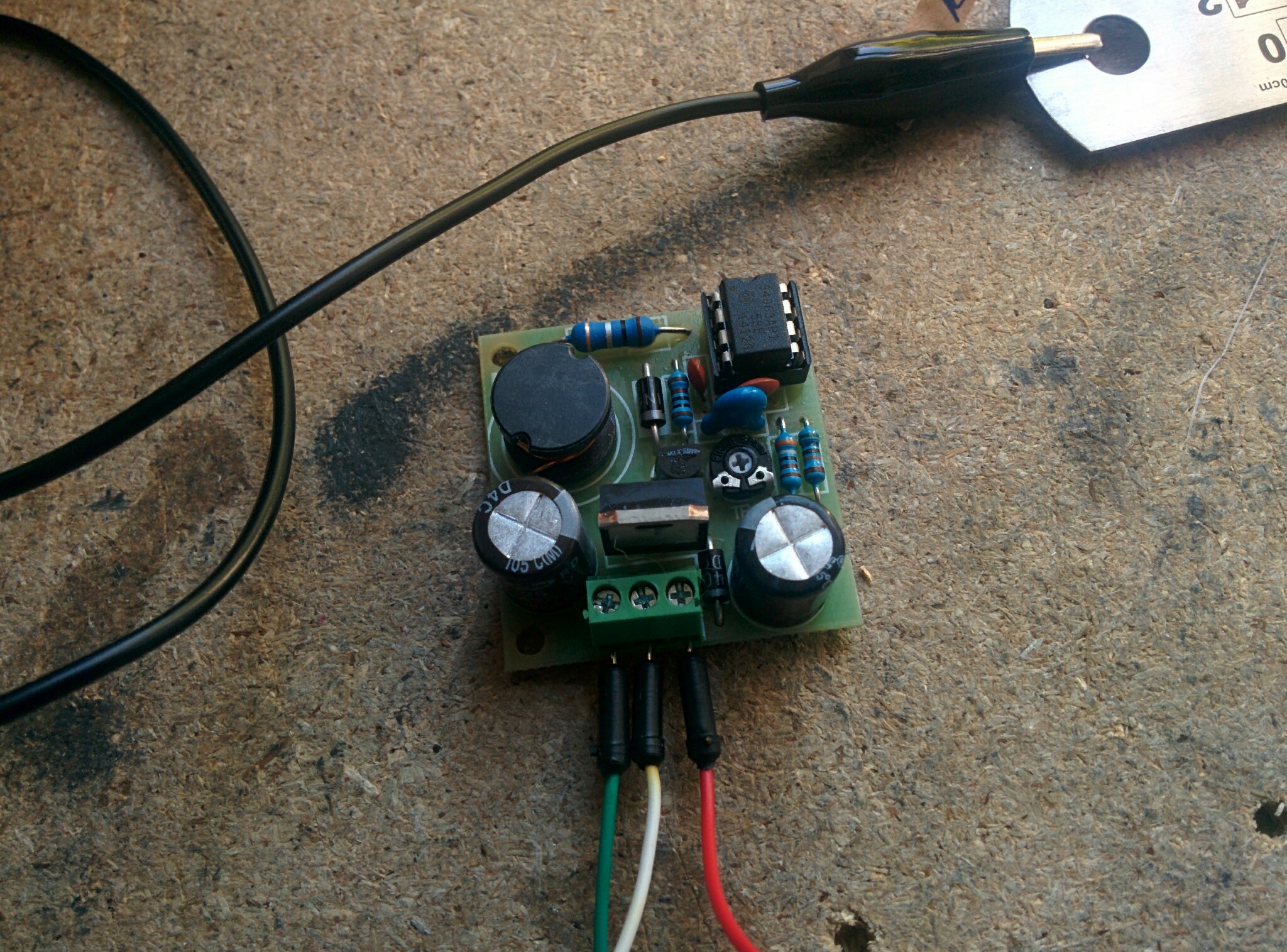
First testing of tubes, in my project I'm using IN-1 Soviet tubes and DC step up 180V

img_20150505_183835.jpg

img_20150505_183845.jpg
 
Register to hide this ad
That's very cool and just a little bit (for this crowd) sick.
I'd be worried about the relays wearing out over time.
There are about 31.5 million seconds in a year - how many cycles is each relay rated for? (Put them in sockets).
 
Relay driven nixies? Cool. Need a seconds indicator so you get a nice regular tick out of it. Good for sleeping purposes.
 
That's very cool and just a little bit (for this crowd) sick.
I'd be worried about the relays wearing out over time.
There are about 31.5 million seconds in a year - how many cycles is each relay rated for? (Put them in sockets).

Not sure I understand the first line.

Also wondered about the relays longevity but still think it's cool. (Hmmm given the first line, what does that say about me? ;)) However, I would think the clicking might get old after a while. At least the hour and maybe minute relays should last a lot longer than the seconds and tens of seconds relays.
 
Well yes you are definitely right about the second situation, I'll see how long they last. I have had relays switchable, but it was causing a lot of switch bouncing (if this is the term) as I didn't design them with opto-couplers (didn't know by then).
Never mind here some progress:

Tubes soviet IN-1 nixies with 3D printed unobtanium sockets. I used Molex connectors for pins. This is 11 pin tube. 1 Anode, 10 Cathodes (0-9)
img_20160519_122734.jpg


Fist testing done, of course nothing was working, but after a little bit of debugging all works, ribbon cables used.
img_20160227_223309.jpg
 
Detail of 0.1" PCB connector. I'm using 15k dropp off resistor for anode to prolog life of tubes. Also tubes are on-off switchable and dim-bright function on front panel.
img_20160228_163131.jpg


This a real high tech wooden block :) Tubes are running, although inputs of relay are manually controlled by 5V for now. 5V via 1K resistor and 2N222 NPN transistor openning ground of relay
img_20160228_180628.jpg

img_20160228_183432.jpg


Of course I would make my own PCB, instead of using prototyping PCB's but that's learning progress. Also these cheap paper pressed PCB's don't look the deal either :)
 
Last edited:
Testing Display and red Perspex display cover 4401 RED, 3mm, A4 (297mm x 210mm) used
Digits are set manually.
img_20160229_163114.jpg

img_20160229_163134.jpg
 
Thank you for kind words and support. I'll post some more pictures then...

First idea / drawing of front panel & button / switch placement.
Front panel is Aluminium 4mm CNC machined gray powder coated with engraving and black infill. Handles chrome plated Hammond 7" steel rack handles.
Rear and bottom 2mm brushed aluminium
Top / sides 1.2mm Aluminium black hammered paint
img_20160302_173951.jpg


Prototyping / testing my idea of Transient display switch on for 20 seconds. Used 555 timer. Relay switching 180V PSU for nixie tubes.
img_20160319_174434.jpg


Now board is done (just lettering missing)
Functionality:
- display on / off with SPST switch
- 20s transient display ON with push button
- dimming display with SPST switch. Every Tube anode with 15k drop resistor, Dimming achieved with with pair of 7.2k resistors, bypassed by SPST switch for full brightness. This is lowest value I could get before digits were still able to display in full shape.
img_20160320_101141.jpg


Now testing in circuit. still long way to go.
img_20160320_141959.jpg
 
Alarm via rotary selectors, I like it. Whats the alarm setup, just a controlled relay to operate whatever external device you tie to it?
 
Back
Top Bottom