• The move to the new server is done. There are some software and database maintenance updates in process. This has us passing the hat around to help out. We appreciate any donations. Seriously, even a dollar helps. The payment page may be found here - https://www.audiokarma.org/support.html

Noble Resistors on Accuphase E-202 main driver board-720-0002-00

fdeelros

AK Subscriber
Subscriber
Hello everyone,
I wanted to resurrect this thread. I need help identifying the part number for the noble resistors on the main driver boards (720-0002-00) of my accuphase E202. One of the TO shorted and cause 2 of the resistors to crack. Is there an upgrade for those resistors and if so what is the part number? Thanks everyone...
 
Register to hide this ad
This is what the schematic says- R28- 31 Cement Coated Metal Plate Resistor RW993FlROJ 1ohm ±5% 3.16W
 
Also, I checked the output transistors and found that out that 2 of the 6 were shorted and caused the damage to the resistors. I replaced them all with Mj1193/94 and the short is gone. The relay clicks as it should, however there is no sound. On a closer check, I realized that 2 of the main filter caps are leaking. I have the replacements that I had purchased from parts connection and will replace the tomorrow. The question is; would that cause the no sound issue? I ordered the manual from stereo manuals and will probably arrive tomorrow. I will let you all know how this went.
 
So your needing some 1ohm 3 or 5W radial jobs. Look at Mouser, Part #660-BPR58C1R0J.

If these resistors are burnt, you'll certainly get no sound. It would also hide any failed drivers. Recommend powering up with a DBT.
 
Thanks EW. I will order the parts and report back with an update. BTW, what about the filter caps issue?
 
If two caps are leaking, they need to go. But if the leaking caps are holding the voltage to a reasonable degree, they aren't likely to be the source of the missing channel.
 
Thanks for the answer Glen. I checked the voltages and they seem to be holding, however I don’t trust them. Are those old caps polarized (+/-)? I could not find any identification as in the new ones. The new ones are properly identified or polarized. I was able to figure out the polarity of the old caps based on voltage measurements and wire colors (red stripe and ground=good voltage and black stripe with ground no voltage), however I am not 100% sure...
 
On the positive supply, wht/red stripe = positive. Other terminal is obviously negative. For the negative supply, wht/violet stripe = negative. Other terminal is positive.
 
Thanks Glen, I will tackle that tomorrow. On another note, I recapped the power supply board and replaced the Tos (679/1079) with MJ1193/94 respectively and the amp clicks ok, however there is no sound. I also replaced transistors Q1,2,3,4,5,6 with ztx649B and Q8&Q6 with 2SC3902T, relay clicks but still no sound. Are those replacements appropriate? please advise, thanks. By the way, if I input signal thru the Main in flip the switch in the back (Normal/separate), I can hear an amplified but distorted sound coming from the speaker outputs. Does that mean that amp part is good and that I should focus on the preamp boards?
 
Sorry I did not see this. With a signal fed directly to the amp through the main-in, you should have a clean, undistorted signal through the speakers. Anything else means amp problems.

So from everything here, sounds like several issues. I'd be looking closely at the power supply voltages for starters.
 
Thanks Glen. I checked the power supply voltages and here is what I got:

1- 0

2- 67.4

3- 67.4

4- 90.6

5- 39.9

6- 90.6

7- 0

8- 0

9- 0.53? not or odd reading

10-(-91.3) negative value

11-0

12-0

13-59.4 - I think this should be 27.4?

14-3.76

15- 90.2

16-0.15?

17-59.4 - I think this should be 27.4?

18-0

19-50.7

20-0

By the way, I asked you abut the transistors I replaced on the power supply, but did not get an answer. There are a couple of readings above that are incorrect and that may be the cause? please advise, thanks again for all your help.
 
Before we delve into voltages...
replaced the Tos (679/1079) with MJ1193/94
You mean MJ21193 and MJ21194 Those are fine for outputs, but if the originals are OK, I'd have let them be.

I also replaced transistors Q1,2,3,4,5,6 with ztx649B and Q8&Q6 with 2SC3902T
I assume we're talking about the power amp. If so, Q1, Q2, and Q6 are PNP, and a 696B are inappropriate here. A Zetex ZTX795A would do.
and Q8&Q6 with 2SC3902T
The ONLY reason to mess with the original TO-66 devices is if they are blown. And Q6 is still a PNP device and the 2SC3902 is not going to work.
 
Thanks for the clarification. I think I messed up when I was trying to explain the transistors replacing. Per your advise, I am focusing first on the power supply (Board 719-0004-00). I recapped the power supply board and also replaced the following transistors: Q1, Q2, Q4, Q5, Q7 with ztx649B. Q8 with 2sc2690A and Q6 with 2sa1220, I left Q11 unchanged. The relay works OK, but the voltages I think are incorrect, according to what I stated earlier. Are those transistors replacement in the power supply board appropriate?
 
voltages doesn't look good. Here are the biggest differences:

4. 79V instead of 90,6V
6. 67V instead of 90,6V
9. -40V (!)
13. should be 55V (so yours 59,4V is not so far away) 17. is bridged and always the same as 13.

Please check again, maybe there was some wrong meassurement.

Responsible for the neagative voltage of -40V are Q10 and 11. SV-02 adjust Ube at Q 10. Check all parts around Q10/11, in my case C24 was weak, i only had -27V. Changing it results in -36V. Then i mounted a variable resistor instead of R35 and adjusted to -40V, resistance was at about 28kOhm instead of 33kOhm. So i replaced this resistor and got the -40V.

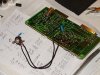
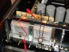
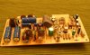
DSC01983.JPG DSC01980.JPG DSC01984.JPG
 
Last edited:
Back
Top Bottom