• The move to the new server is done. There are some software and database maintenance updates in process. This has us passing the hat around to help out. We appreciate any donations. Seriously, even a dollar helps. The payment page may be found here - https://www.audiokarma.org/support.html

Nobsound 6p1 Amp flaws/mods

Thanks for quick replying. I thought the ground was the red wire at the T. I'm glad out of all the new digital tech out there that these are simple to work on.
 
First off, I would like to thank you for the series of videos on the Nobsound 6p1. After watching your videos, I was curious and bought the same amp with the added headphone output.
Would I be able to do the mode using the same part list?
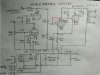
I was able to acquire the schematic here:
This is the photo of the amp:
Thank you very much!
71xI6NomJ9L._AC_UL320_SR320,320_.jpg DJ420 & DJ428.jpg
 

Attachments

  • DJ420 & DJ428.jpg
    DJ420 & DJ428.jpg
    117.7 KB · Views: 28
First off, I would like to thank you for the series of videos on the Nobsound 6p1. After watching your videos, I was curious and bought the same amp with the added headphone output.
Would I be able to do the mode using the same part list?

That looks like the same schematic, I'm curious how they implement the headphone jack.
 
I just purchased one of these from ebay. It came with the rectifier tube, has a bad volume potentiometer. I also noticed the one of the 270ohm resistor the runs parallel with 220uf 50v cap is burnt. What is the size on these resitors?

Thanks
 
I just purchased one of these from ebay. It came with the rectifier tube, has a bad volume potentiometer. I also noticed the one of the 270ohm resistor the runs parallel with 220uf 50v cap is burnt. What is the size on these resitors?

Thanks

2W
 
Now I have a question about the resister mod you did. The resister you moved crosses through the output tube from left to right 2 spaces away from the coupling cap on either side. Please forgive me as I am not looking at a schematic. I don't know the pin out. Should that wire remain after moving the resister or remove it?
 

Attachments

  • IMG_20210727_125141629.jpg
    IMG_20210727_125141629.jpg
    138 KB · Views: 58
Got done with mods and replacing burnt resistor a few weeks ago, used metal films since thats what I had on hand.

Tubes from Ukraine finally arrived!

Do all the tubes have to be installed for powering on to double check voltages or just the rectifier tube?IMG_20210807_095150.jpg
 
So powered on with all tubes, no smoke:banana: Voltages seem to be ok, I matched both left and right. One thing doesn't seem right is the heater voltage, it's reading 3.4v not 6.3v.

I did proceeded to hook up to my daughter's system and a very slight thump when turned on. No output to speakers.

The meters on the front, How do they work? Do they measure the input signal?
 
So powered on with all tubes, no smoke:banana: Voltages seem to be ok, I matched both left and right. One thing doesn't seem right is the heater voltage, it's reading 3.4v not 6.3v.

I did proceeded to hook up to my daughter's system and a very slight thump when turned on. No output to speakers.

The meters on the front, How do they work? Do they measure the input signal?

Hello @wendell . Can you confirm what are the other voltages you are getting from the transformer.

It is weird. It looks like you might have a 220v transformer. Assuming you are using a voltage regulator to step down 126v to 116v. Then 116v/220v*6.3v=3.32v on the heaters.
 
The heater voltages on the (2) 6SN7 along with the (4) 6p1p = 3.4VAC
The 5U4C rectifier tube heater voltage= 279.6VAC?
 
The heater voltages on the (2) 6SN7 along with the (4) 6p1p = 3.4VAC
The 5U4C rectifier tube heater voltage= 279.6VAC?

Ok. Did you measure directly on the 2 tube heater pins? Or between transformer tap and ground? Or between both transformer taps? Because I believe the transformer produces -3.3v and 3.3v which is seen as 6.6v on the heaters.
 
Ok. Did you measure directly on the 2 tube heater pins? Or between transformer tap and ground? Or between both transformer taps? Because I believe the transformer produces -3.3v and 3.3v which is seen as 6.6v on the heaters.
I measured on the tube socket pins where all the wires are soldered. So the heater voltages should be good on the 6SN7 and 6p1p.

What's going on with the recitifier heater voltages? Are they suppose to be that high?

Any ideas why I'm not getting any output to speakers? I'm gonna try another source.
 
I measured on the tube socket pins where all the wires are soldered. So the heater voltages should be good on the 6SN7 and 6p1p.

What's going on with the recitifier heater voltages? Are they suppose to be that high?

Any ideas why I'm not getting any output to speakers? I'm gonna try another source.
The rectifier heater voltage should be 5v at the pins.

@StepheK do you any idea of what could be happening?
 
So I measured the rectifier voltages again from the tube socket. I had the voltages mixed up, here they are

Pins 4&6 are 276.2VAC this is from the tX.

Pins 2&8 are 29.86VAC this is for the heater.
 
Back
Top Bottom
