

You are using an out of date browser. It may not display this or other websites correctly.
You should upgrade or use an alternative browser.
You should upgrade or use an alternative browser.
Ok to change these caps? Scott 222D
- Thread starter aedaza
- Start date
Register to hide this ad

ferninando
Lunatic Member
yes
ferninando
Lunatic Member
pics please.
Ive refurbd a scott 222B and bought a scott 299B. However I left the "bias" caps alone(for now) in the 299. Made up of 4 1oouf caps. All the bias voltages are spot on.
Ive refurbd a scott 222B and bought a scott 299B. However I left the "bias" caps alone(for now) in the 299. Made up of 4 1oouf caps. All the bias voltages are spot on.
ferninando
Lunatic Member
BuzzK, you mention a V-drop R when going from selenium to silicon bias rect.
I did(FWB from RS) in the 299 but all the high voltages remained UNDER the schem values by typically 20-30 volts. All caps replaced as well. Does that indicate a need for a V-drop R? And where in the ckt does it go?
Don't mean to HJ thread but is related to it.
I did(FWB from RS) in the 299 but all the high voltages remained UNDER the schem values by typically 20-30 volts. All caps replaced as well. Does that indicate a need for a V-drop R? And where in the ckt does it go?
Don't mean to HJ thread but is related to it.
ferninando
Lunatic Member
well the 299B runs 6BQ5s at 55ma and they set spot on/per scott instructions and DC bal..
The PSHV voltage is measured statically/no sig in and remains at lower than schematic values. Nothing I do seems to make a diff. Now there's not athing wrong with SQ, power or anything. Was just telling of existing conditions for V-drop R info. It would seem one is not needed in my situation. But Im no xpert so Im open to input.
Thanks.
PS: its a factory wired unit unmolested and all the bias voltages are spot on.
The PSHV voltage is measured statically/no sig in and remains at lower than schematic values. Nothing I do seems to make a diff. Now there's not athing wrong with SQ, power or anything. Was just telling of existing conditions for V-drop R info. It would seem one is not needed in my situation. But Im no xpert so Im open to input.
Thanks.
PS: its a factory wired unit unmolested and all the bias voltages are spot on.
ferninando
Lunatic Member
If it's not an issue, then why the fuss?
no fuss man just asking! you raidsed the issue about vdrop R.

aedaza
Active Member
Pics? You askedd for it!
First one is the top of the Scott 222D.
Second pic, one of the Unisound caps in question.
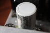
Third, third pic of a cap under the Scott that I dont know what it is supposed to do... It is that large black and ugly cap next to the transformer. I ask because it looks really bad. I suppose I have to replace it, but what does it do? What can I expect if this cap has been bad? With what values can it be replaced?
Fourth, the JJs I was talking you about.
Thanks!
Alex
First one is the top of the Scott 222D.
Second pic, one of the Unisound caps in question.
Third, third pic of a cap under the Scott that I dont know what it is supposed to do... It is that large black and ugly cap next to the transformer. I ask because it looks really bad. I suppose I have to replace it, but what does it do? What can I expect if this cap has been bad? With what values can it be replaced?
Fourth, the JJs I was talking you about.
Thanks!
Alex
Attachments



Last edited:
tube-a-lou
Addicted Member
Hi,
I had a 222C and I think that's to much for the Scott, I put in two 50/50, the original
is about 20/20, so 50/50 is ok but 100/100 to much of a good thing.
Tube
I had a 222C and I think that's to much for the Scott, I put in two 50/50, the original
is about 20/20, so 50/50 is ok but 100/100 to much of a good thing.
Tube

Except for the one stage that is DIRECTLY connected to the 5AR4 (i,e, the very first cap section after the rectifier tube), 100uf is just fine.
5AR4s are only rated to 60uf max, for that first cap section. I'd stick to that recommendation, for long tube life. No point in killing the tube before its time...
Regards,
Gordon.
5AR4s are only rated to 60uf max, for that first cap section. I'd stick to that recommendation, for long tube life. No point in killing the tube before its time...
Regards,
Gordon.
tube-a-lou
Addicted Member
Thanks Gordon
tube-a-lou
Addicted Member
Hi Alex,
There made by JJ Electronics, There from Europe there a nice cap.
Tube
There made by JJ Electronics, There from Europe there a nice cap.
Tube
aedaza
Active Member
Hi Alex,
There made by JJ Electronics, There from Europe there a nice cap.
Tube
Thanks Tube, but I am talking about the black one on the third pic in my post where I include the pics. It looks kind of bad... More than the rest.
Thanks,
Alex

kvflyer
Super Member
Two things come to mind.
Gordon is certainly right. You don't want to stress the 5AR4/GZ34 with a capacitor that is too high in value if it is connected directly to its cathode. Some Scott amps may have a resistor first after the rectifier tube and it can act as a current limiter. But I would not be too "creative". JJ makes capacitors in 32-32uFD @ 500 WVDC and 50-50 uFD @ 500 WVDC so you have choices.
And If I understand correctly, after the selenium bridge was replaced with silicon, the voltage was low? I f so, it could be that the filters after it are weak (have a high ESR) or even open. It may need replacement as well. They are often not too bad. But I have found them to be bad too. I found some thin 100 uFD @ 100 WVDC that fit nicely inside of even the short bias can. (Some of those caps are as big as the B+ filters.
Hope I am not saying the obvious and repeating. I am working on a small Netbook in Australia (visiting my daughter and family) and it is very difficult to type and navigate, not to mention that they charge by the byte download here!
BTW, It doesn't get much better than the Scott amplifiers!!!
Gordon is certainly right. You don't want to stress the 5AR4/GZ34 with a capacitor that is too high in value if it is connected directly to its cathode. Some Scott amps may have a resistor first after the rectifier tube and it can act as a current limiter. But I would not be too "creative". JJ makes capacitors in 32-32uFD @ 500 WVDC and 50-50 uFD @ 500 WVDC so you have choices.
And If I understand correctly, after the selenium bridge was replaced with silicon, the voltage was low? I f so, it could be that the filters after it are weak (have a high ESR) or even open. It may need replacement as well. They are often not too bad. But I have found them to be bad too. I found some thin 100 uFD @ 100 WVDC that fit nicely inside of even the short bias can. (Some of those caps are as big as the B+ filters.
Hope I am not saying the obvious and repeating. I am working on a small Netbook in Australia (visiting my daughter and family) and it is very difficult to type and navigate, not to mention that they charge by the byte download here!
BTW, It doesn't get much better than the Scott amplifiers!!!
aedaza
Active Member
Thanks Tube, but I am talking about the black one on the third pic in my post where I include the pics. It looks kind of bad... More than the rest.
Thanks,
Alex
Anyone??:scratch2:
ferninando
Lunatic Member
Anyone??:scratch2:
IMO if it's an old electrolytic, change it and move on.
Best preventative medicine for these old amps.
Use equal value C but higher value voltage is OK.
I did some modeling on the 222D in Duncan PSUD2.
Since the 222D has a 20 ohm 10w resistor immediately after the 5AR4, that "cushions" the rectifier from current spikes a bit, making it possible to stretch the normal capacitance limit for the 5AR4, a bit.
I found, that if you use a SINGLE 100uf section to replace BOTH 20uf parallel sections at the output of the 20 ohm 10w resistor (going from 40uf to 100uf), the rectifier will still be within spec (does not exceed .75a max peak current, rated for the tube). But, just barely. In case of rectifier arcing, you can replace the 20 ohm 10w resistor, with one between 33 and 40 ohms (still 10 watt), and it will reduce the peak loading on the rectifier by about 10%, while only dropping a max of about 12v from B+ (hardly noticeable, if at all, in terms of peak power output of the amp).
The can caps in this amp should either be a 4-section 20uf and a 2-section 20uf, or two 3-section 20uf caps... for a total of six 20uf sections. If those are replaced by two 100uf 2-section caps... then, one more section will be needed. You can replace the 20uf x 2 paralleled section with one 100uf as mentioned above, and the next three 20uf sections with the remaining three sections (one in the first cap, both in the second cap), but you will need one more cap (say, 47uf at 350v or so, mounted under the chassis) to replace the last one in line. Here's the original power supply diagram for the 222D, modified to show this arrangement:

This should work OK...
Regards,
Gordon.
Since the 222D has a 20 ohm 10w resistor immediately after the 5AR4, that "cushions" the rectifier from current spikes a bit, making it possible to stretch the normal capacitance limit for the 5AR4, a bit.
I found, that if you use a SINGLE 100uf section to replace BOTH 20uf parallel sections at the output of the 20 ohm 10w resistor (going from 40uf to 100uf), the rectifier will still be within spec (does not exceed .75a max peak current, rated for the tube). But, just barely. In case of rectifier arcing, you can replace the 20 ohm 10w resistor, with one between 33 and 40 ohms (still 10 watt), and it will reduce the peak loading on the rectifier by about 10%, while only dropping a max of about 12v from B+ (hardly noticeable, if at all, in terms of peak power output of the amp).
The can caps in this amp should either be a 4-section 20uf and a 2-section 20uf, or two 3-section 20uf caps... for a total of six 20uf sections. If those are replaced by two 100uf 2-section caps... then, one more section will be needed. You can replace the 20uf x 2 paralleled section with one 100uf as mentioned above, and the next three 20uf sections with the remaining three sections (one in the first cap, both in the second cap), but you will need one more cap (say, 47uf at 350v or so, mounted under the chassis) to replace the last one in line. Here's the original power supply diagram for the 222D, modified to show this arrangement:
This should work OK...
Regards,
Gordon.
Attachments

Last edited:
Excessive heat (red-plating) would be another sign the 5AR4 is not happy.
And yes... .75a max PEAK current (225ma max CONTINUOUS) is standard for all 5AR4. Though, on currently produced units (from China and Russia), I like to back off from that about 10%, because they do not seem to handle overload as well as the originals made back when the amp was new. That would be where the 33 to 40 ohm resistor would probably be needed.
As for your other issues with caps... if you'll post up what you have, we should be able to help you in getting those caps allocated as well as can be, for what you have left to do. You may not necessarily need to buy more stuff...
Regards,
Gordon.
And yes... .75a max PEAK current (225ma max CONTINUOUS) is standard for all 5AR4. Though, on currently produced units (from China and Russia), I like to back off from that about 10%, because they do not seem to handle overload as well as the originals made back when the amp was new. That would be where the 33 to 40 ohm resistor would probably be needed.
As for your other issues with caps... if you'll post up what you have, we should be able to help you in getting those caps allocated as well as can be, for what you have left to do. You may not necessarily need to buy more stuff...
Regards,
Gordon.


