• The move to the new server is done. There are some software and database maintenance updates in process. This has us passing the hat around to help out. We appreciate any donations. Seriously, even a dollar helps. The payment page may be found here - https://www.audiokarma.org/support.html

One giant leap for a man, one small step for mankind - learning how to solder

Vlad Soare

Politically incorrect since 1976
Subscriber
Hi guys,

I've been a technically inclined person all my life. As a kid, what I wanted most was to understand how stuff works, what makes it tick. I learned how to use a screwdriver before I learned to write. I've always been good at fixing stuff. I loved (and still do) working on my car, fixing it, improving it, doing my own maintenance work, etc. However, I had one big, big Achiles' heel. One major pain point.
I've always been utterly useless with a soldering iron. I could never solder something to save my life.

It's not that I didn't try. I did. Many times. I tried soldering irons and soldering guns. Cheap ones, or slightly more expensive ones. Sometimes I couldn't even get the solder to melt. Other times it did melt, but then formed little balls that simply fell down instead of spreading evenly on the tip. Most of the times the tip went from shiny to black within seconds. Sometimes I managed to tin the tip, but not to melt solder on anything else. And then the shiny, newly tinned tip turned black again. I tried getting a more powerful iron. To no avail.
I read a lot about it, I knew the theory, but somehow my experience didn't seem to match the theory. Somehow I was unable to turn the theory into practice. The soldering gods just did not want me to do it.

Consequently, all my life was spent avoiding any kind of work that involved soldering. Or, if it did involve it, trying to find a workaround. I would go out of my way to use connectors, crimps, anything, just not to solder. Sometimes I would even wrap the ends of two wires around each other, then cover them in insulating tape. Ghastly, I know. I'm ashamed to even think about it. I used to take so much pride in the quality of my work, in my attention to details, only to ruin it by doing such a horrible job when it came to connecting two wires together.
Of course, electronics were completely out of the question. For me, a PCB has always been a black box. Something that other people made, and that simply worked. Until it didn't. When it didn't, it was time to send it to the bin. I knew that those tiny components could be desoldered and replaced, but that was a job for other people.

Until now. About two weeks ago I decided I just couldn't take it anymore. I will learn to solder, if it's the last thing I do. I read a lot of articles, reviews of various tools, watched a lot of videos, got myself a temperature controlled soldering station, some solder, and got to work. With very limited success - but at least it was a bit better than before. At least there was hope. Then I got myself an even better soldering station, with T12 tips. And ditched the lead-free crap and got some proper leaded solder. Now we're talking! What used to barely work at 400 °C before, was now a piece of cake at 315 °C.

I also ditched my cheap desoldering pump and got a properly good one. Plus some helping hands. Plus some flux and solder wick. I tried to use the cheap loupe that came with the helping hands, but I didn't like it, so I bought a pair of magnifying glasses. I had a defective switching power supply lying around. I cracked it open, took its PCB and started desoldering and resoldering the components. It took a while, but in the end I got the hang of it. Two or three days later I was able to desolder a component reliably and to solder it back perfectly.

Then I looked online for some cheap DIY kit that I could build myself, and found one for less than 4 dollars including shipping. It was supposed to be a pulsing LED heart.

(to be continued)
 
Last edited:
Register to hide this ad
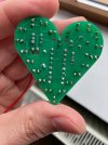
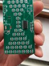
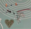
This is how the kit looked. Just a PCB and a collection of components.

IMG_2376.jpeg

IMG_2377.jpeg

There were no instructions, but everything is clearly marked on the PCB, so I was good to go.

(to be continued)
 
OK, so there are six resistors, whose location is marked on the PCB. But how to know which is which?
The 47K resistors were easy to identify, simply because there were three of them, while the others were one of each type. So, the three identical resistors must be the 47K ones. But how about the others?
I looked online and found out about the color coding. Found a good chart and was then able to identify each resistor.

The LEDs have a positive and a negative lead, but which is which? I searched online and found that the positive lead of a diode is supposed to be longer. Indeed, the supplied LEDs had one leg longer than the other. Marvellous.

The capacitor had the negative lead marked. And to make it even clearer, the unmarked lead was a bit longer than the marked one.

The chip had a little indentation to show the correct orientation, an indentation which is also represented on the PCB. So did the power switch.

OK, so everything is clear. But now, the resistor leads must be bent. How to bend them safely, and at precisely the right spot? I looked online and found that there are tools specifically made for this purpose. Of course I didn't have one, so I needed to find an alternative solution. Some people said bending them by hand is a no-no, because it can cause the lead to break at the connection point to the resistor. Needle nose pliers didn't work, because the "needle" nose wasn't exactly like a needle when put beside the tiny resistor. Luckily I had a pair of tweezers that did the trick.

Now, to trim the leads before or after soldering? I did some reading on the subject and found that there isn't a consensus in this respect. I decided to trim them before soldering, in order to avoid the risk that a joint shatters when doing the trimming. But then how to hold the components in place? Bending the leads outwards to keep the component in place doesn't work if you trim them first. I decided to use sticky tape, which seemed to work not quite perfectly, but at least well enough. Next time I'll use Blu Tack. I've ordered some in the meantime.

Next issue - how long (or short) to cut the leads? Too short, and they will be completely covered in solder. Too long, and they will look ugly. The problem was made worse by the fact that the sticky tape held the components in place only approximately, not very firmly. Sometimes I trimmed the leads to what looked like the perfect length, only to have the tape sag a little and cause them to be too short. Other times I trimmed them longer, to allow for the tape sagging, only to have the tape work magnificently and not move a bit. :rflmao:
This is why you'll see that the amount the leads stick out of the joints is all over the place. Some are perfect, some are too long, some are even completely buried in the joint.
I hope next time, since I will have Blu Tack at hand instead of the lousy tape, I'll do a better job.

Another problem was that, as you'll see in the pictures, the LEDs are installed right at the very edge of the PCB, which means that as I was installing them I was slowly running out of space to hold the PCB. I know there are holding devices meant specifically for PCBs, but I didn't have one All I had were some crocodile-style helping hands, and once the LEDs are in place there's not enough of a lip left to attach the crocodiles.
In the end I did it, but it wasn't easy. I then went online and ordered a PCB holding device. So next time I'll hopefully not have this problem again.

(to be continued)
 
Last edited:
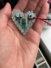
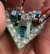
And here's the end result:

IMG_2381.jpeg

IMG_2382.jpeg

IMG_2383.jpeg

IMG_2384.jpeg

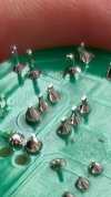
Only now, looking at this photo, do I notice the starved joint. I missed that. I'll fix it. But the thing works nonetheless.
Here it is:


The uneven light and the out-of-sync pulsing are artefacts of my phone camera. To the naked eye they look equally bright, and they pulse in sync.
 
Last edited:
Now, I know that for most of you soldering is second nature. I'm amazed at the kind of work you do with extremely complex audio stuff. My coming here to brag about having built a small simple toy is like going on a professional cooking forum to boast about my first omelette. :biggrin:

But for me it's a big step. It took me fifty years to learn how to use a soldering iron properly. :eek:

Next, I'll work on trimming the leads to more precise and uniform lengths. And on checking the joints more carefully, so I won't miss bad ones anymore.
And of course, I need to work on actually understanding what I'm building. Right now I have absolutely no idea how this thing works, why those precise components were used, and why they were placed the way they were. I just followed the instructions blindly. I'd love to also understand how this stuff works, and maybe to build something designed entirely by me.

And who knows, maybe some day I will gather up the courage to look into SMD soldering as well. :idea:
 
Last edited:
Good for you! I think you did a very good job and especially so since you are so inexperienced.

I fall into the "second nature" category that you mentioned.

I was first exposed to soldering electronics by my stepmom when I was a kid in the 70's. She was populating thru-hole boards at home to make extra money and showed me the basics. I quickly got good enough to help her.

Jump ahead to 1986 and I get hired by Sperry on Long Island -big defense company making stuff for the US Navy- as a electro-mechanical assembler. They put me through a week of MIL-STD 454 solder training/certification as both an operator and an inspector. That was later updated to MIL-STD 2000.

Then, in the late 90's, I started working for a start-up digital communications company in Scottsdale as a senior tech. This is where I got my first exposure to SMT. I was lucky enough to work with a really nice and talented woman who was our assembler/re-work dept. She showed me the SMT ropes and I did lots of SMT assembly/repair/prototyping.

My personal soldering zenith came when I was working for a different place in Scottsdale. The boards were very complicated, super dense and heavily populated. I forget the exact reason why but a bunch of capacitors needed to be added. The only was this could be done in a prototype was to attach them to vias on the bottom side of the board and then tie them to ground. The chip in question was a BGA package and had no exposed leads. My task was to solder about a dozen 0402 ceramic caps, standing up one one end, to the various vias under the chip in question. After soldering the caps to the board, the next step was to string a fine wire from cap to cap to cap and finally to a ground via.

The job I finally retired from require a mix of SMT and thru hole skills to repair stuff and I did my share of prototyping.
 
:) well done .
Tip : next time put the leads through the holes , push the part against the board an bend the leads slightly outwards .
This will keep the part in place ( no tape or blu tack needed ) , solder and snip off the excess using flush cutters .
Regards F.
 
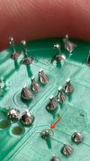
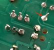
Only now, looking at this photo, do I notice the starved joint. I missed that. I'll fix it.
Actually, it's not starved. It's just an optical illusion. That's why I didn't notice it - there was nothing to notice. :biggrin:

IMG_2384 copy.jpeg
It certainly looks starved, doesn't it? But it's just the shadow of the lead stub and the reflection of the board that give this impression. Here's how it looks from the other side:

IMG_2389.jpeg

The bottom right ones, on the other hand, look ugly indeed. I've no excuse for those. :)
 
Yes yes yes yes! This is the way!

Those little kits are the best way to learn how to solder, and the can be awesome for just getting a feel of how it all goes. And kudos for good tools. Priming yourself for success at this stage is a wise move.
 
Thank you all for your kind words. :beerchug:

Regarding this:
And who knows, maybe some day I will gather up the courage to look into SMD soldering as well. :idea:

Well, it appears that that day has come much sooner than I expected. :rflmao:

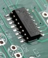
I wasn't planning to move on to SMD yet. You know, don't try to run before you can walk... And I've barely learned how to walk. But as I opened the next DIY kit and looked at the components, I noticed one tiny chip. Everything else is THT, except this teensy-weensy chip, which is SMD. Oh my god! What do I do now? :eek:
Should I give up? Solder everything else just for training purposes, but leave this chip out, even though the device won't work in the end? Or put the kit aside and tackle it later on, when I'm ready?

I decided to watch some videos again and to give it a try. After all, what do I have to lose?

So, here's my first attempt at drag soldering. :cool:

IMG_2392.jpeg

IMG_2393.jpeg

IMG_2395.jpeg

To be fair, this wasn't exactly my first attempt. The first attempt was a bit messy, having used too much solder and having created some bridges. I used solder wick to remove the excess and then touched up a little.
 
It is now complete, but unfortunately I can't show you how it works, because it doesn't anymore, due to my stupidity. :(

IMG_2396.jpg

IMG_2397.jpg

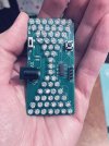
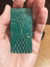
It's supposed to be an hourglass. When you turn it on, the upper half of the LEDs light up. Then slowly, one by one, they move down until the upper half empties and the lower one fills up. Then it starts over. The switch on the left side turns it on or off, while the little button on the right changes the speed. It is powered through a 5V round connector.
I didn't have a 5V power supply with a round connector lying around, but I did have a USB-A to round adapter cable. And one of my power cord extensions happened to have a USB-A outlet. I connected it there, and it worked like a charm. Lovely.

But that power cord was under a table in my living room. I couldn't make a video down there, on my knees, in semi-darkness. Then I remembered I had a power adapter for charging a handheld vacuum cleaner. That adapter had a round connector, and the other end of the cable went into a switching power supply with a USB-A plug - which means it must be the correct voltage, right? Wrong, as it turns out.
I plugged that into my new toy, and it didn't work. Only half of the LEDs lit up, and there was no animation. Then I noticed something. The cable came indeed from a USB-A plug, but it wasn't just a dumb cable. There was a bulge on it, and a label on that bulge stated "9V". I measured it with a multimeter, and sure enough, it took 5V in and put 9V out. :yikes:

So I ruined it before having a chance to film it and show it to you. :(

Now a few of the LEDs measure less than the others. They show a forward-biased voltage of about 1.7V, while all the others are around 2.5V, give or take. And of those that do measure correctly, about half don't light up anymore despite the correct voltage.
Aaaargh!!!!!! :rant:

Well, at least I have seen it work, so I know that my soldering was fine. Even the SMD part. :cool: :smoke:

But it's still frustrating. How could I be so dumb and not pay attention to the voltage of the power supply? This is electricity 101, for God's sake! :(
 
Last edited:
What I have learned during this second exercise:

1. A PCB holder is worth its weight in gold. It was sooo much easier to work with it than with the crocodile-style helping hands.

2. A medium-sized blade-type soldering tip is much better than a conical one. The first time I used a very thin, almost needle-like, conical, because I thought it would fit better in the tiny spaces between the joints. Which was correct, it did fit perfectly, but it was also more difficult to put enough heat into the leads and pads. A blade tip made it embarassingly easy, almost as if they soldered themselves. And the contact time has reduced from three or four seconds to less than two. In, add solder, out, all in the blink of an eye. Despite its larger size, I found I had no trouble placing it accurately at the desired spot.

3. SMD isn't really as scary as it seems.

4. Using the right tip for each job, rather than a jack-of-all-trades conical, is key to working reliably and comfortably. A thin conical for tacking the corners of an SMD chip in place before soldering it properly. A small to medium size blade for THT components. A wide(ish) chisel for drag soldering (though in the future I may also get a bevel or a spoon for that task). The ability to change tips on the fly is a great feature.
 
Last edited:
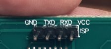
Any idea what this is? I have soldered these four pins at the indicated location, but I don't know what they're supposed to do.
What do those labels mean? I take it GND means ground, but what about the others? And a ground for what?

IMG_2399.jpg
 
Copied from a Google search...

GND, TXD, RXD, and VCC are the 4 standard pins used for USB-to-TTL serial UART communication, enabling computer-to-microcontroller data exchange. They represent Ground, Transmit Data, Receive Data, and Voltage Common Collector (power), respectively. Proper connection requires crossing TXD to RXD and vice-versa.
 
Oh, so the idea is to connect it to a computer and to control or reprogram the chip? That's nice. Or at least it would be nice, if they also provided some documentation. Otherwise, how to communicate with it is anyone's guess. :biggrin:

Edit: actually no, I searched for STC 15W204S and found the documentation. So it's okay.
But of course, that's a moot point if the device is toast.
 
Last edited:
Maybe you can practice repair work!! Buy a new chip and swap it and go from there.
I'd love to. In fact, this is what prompted me to try and develop my soldering skills. I had a couple of smart light switches that I used for controlling some desk lamps remotely from my phone. I loved them. But they were poorly made and failed quickly. And when they did, I had to throw them away. One of them had an obviously blown capacitor, it was swollen and cracked. Maybe replacing that capacitor would have fixed it. But replacing a capacitor was deemed above my pay grade, so into the bin it went. :(

And then I didn't buy replacements, because I thought if they're badly made and fail again, then I'll just waste my time and money. But if I were able to solder and desolder properly, then maybe I could replace the failing components with better ones, and then it won't fail again.
I'd love to be able to fix at least small, simple electronic things like this.

Audio stuff is a different matter, because that requires much more than just knowing how to use a soldering iron. That requires deep knowledge of electronic circuits, which I currently lack. I do have a basic understanding of what the various individual components are, what they do and how they do it, but I don't know what their exact purpose is in a specific circuit. I don't know how to read schematics. I mean, I can "read" them at secondary school level, like, "here's a 47K ohm resistor, which is in series with a 100uF capacitor, all of which is in parallel with that diode, etc.", but I have no idea what that particular arrangement is supposed to do, and how to figure out why it doesn't.
Who knows, maybe in time I will be able to learn this, if I can lay my hands on a good book or something. But for now audio stuff is way out of my reach. I will be very happy if I can at least fix a smart light switch, or a switching power supply, or something like that. :)
 
Last edited:
Back
Top Bottom