


You are using an out of date browser. It may not display this or other websites correctly.
You should upgrade or use an alternative browser.
You should upgrade or use an alternative browser.
Onkyo A5 repair - preamp dropped right channel
- Thread starter klamsoss
- Start date

klamsoss
Be willing to fail and try again.
Have you used them in similar applications?
I don't know how or why things went poorly when I put the replacement op-amp in. No fuses blow, so there are no shorts, but I'm not getting anything like the correct voltages at the transistor legs. The schematic isn't that well marked for test voltages but as mentioned above, at least the primary DC voltages (B1+/B1-) are correct.
But since the voltages on ALL of the legs of both transistors are off, I'm not really sure it makes sense for the transistors to be the only (or main) problem. I don't know what else could be the issue, though.
klamsoss
Be willing to fail and try again.

I can't get the correct voltage at the collector of Q501. I replaced the transistor with TTA 004B, (and the compliment) and all other voltages are correct on the emitter and base, as well as B1+/- and B2+/-. The voltages on Q501 (now a TTC 004B) are all correct across EC and B.
I replaced R501-505, the capacitors, the zener diodes... I'm just still getting around 16.8 VDC at the collector of Q501. I don't understand what's wrong.
Unless and until I get that fixed, I won't have power to the IC
HALP!!!
What am I missing here?
klamsoss
Be willing to fail and try again.
I am hoping someone can help me figure out why the voltage at the collector of Q501 is low. The B1+ voltage is around 40 VDC, so that's not quite the 43 indicated in the spec, but it's comparable to the -41 VDC I have on B1- and Q502 is getting about -24 VDC, so I feel like it's isn't the main bias voltage supply that is the problem. I have checked all the diodes there, anyway, and the dropping resistors that come off of the B1+ supply in the DC Power Supply area indicated in my last post were all replaced. They tested fine, but you never know when a component will be fine on the bench but squirrely in use.
For reference, Q501 was replaced with a TTC004B and Q502 was replaced with a TTA004B. This got things back into line for all the transistor legs of those two semiconductors, except the collector of Q501, which is measuring around 16-17 VDC, not the 26.5 VDC that it should (or commensurate with the -24.8 VDC I get on the collector of Q502, which comes off B1-)
So, I've replaced the TA7136P with the op-amp chip and adapter, as referenced in post #15. The haywire numbers I was getting on the power supply transistors have been resolved by replacing them as outlined above, but I suspect the issue with the voltage on collector of Q501 is the source of the problem for there being no voltage at pin 1 of the replacement IC. Is it possible that there is something downstream causing the issue?
What else should I be checking?

Does it work?
A couple of ideas, but not concrete solutions. First - I believe the voltage missing at pin 1 of the replacement IC is probably meaningless - I am guessing that pin 1 isn't used, as it is only for HF compensation and not for signal or DC levels (see if it is even connected to the IC on the replacement PCB.
My guess would be something is still drawing more current than it should be. My math says normally should drop about 15 volts across R503 which is about 30 mA. or about 7.5 mA per IC. Now you are getting about 25 volt drop, or about 50 mA. My guess would be either the replacement drops more the 20 mA, or one of the other ICs are not up to snuff, and loading down the supply. I suspect the supply is ok, and the voltages are due to loading by one of the ICs (or maybe solder bridge or leaky cap, but not likely.) If you are up to it, try unsoldering the power (pin 7 leads) of the ICs to see if one is still loading the supply down.
klamsoss
Be willing to fail and try again.
Thanks for the input @sregor
I can post the full schematic if that would help... In fact, I will definitely do that later, when I get on my computer that has all my schematics, service manuals, and other data.
I am still getting no output on that side. No signal at any of the signal pins on the replacement IC. I hadn't considered that the other IC, which I have not yet replaced, could be pulling down current and causing the issue. I wanted to get the original problem fixed before I went ahead and replaced all of the TA7136P chips with the op-amp substitute, but I guess I should go ahead and see if that resolves the issue.
You're obviously correct that something is drawing more current than it should, but there isn't a lot there to do it, at least in the power supply. The current HAS to be going through R503 for there to be such a voltage drop, so it makes sense that the other IC chips fed by B1+ are the only possible culprits. I checked carefully for solder bridges and even scrubbed the board down to get residual flux off there, which can sometimes cause weird issues... Those can be ruled out, although a broken trace somewhere could be a factor, in theory. The prior owner replaced all the caps except the ceramic caps, which seldom go bad. That doesn't mean there isn't a leaky one, though.
Anyway, I can definitely pull pin 7 from the other IC (the remaining TA7136) and see what we get.
I will say that I get spec voltage at pin 1 on the other channel TA7136 chip.
I will report back this evening, but I welcome further input!
klamsoss
Be willing to fail and try again.
The schematic page is posted below. I can confirm that I get about 16 volts on pin 1 of all 3 of the other IC chips (the remaining TA7136 chips) but I get 0 volts on the first pin of the op-amp. You were correct about the adapter not even having anything connected at pin 1, so it seems like there's no more reason to pursue that issue.
I was getting correct voltages elsewhere on the op-amp adapter pins, but I wasn't getting a reading on my frequency counter when I put a signal though. I figured I would just hook up speakers and see if I can hear something that I'm not seeing on my meters. Lo and behold, there is now sound from the right channel. It's weaker than the left, and it's distorted, but there is sound, so that's an improvement.
For the record, I went ahead and replaced the other TA7136 chip with the op amp. In fact, I moved the one from the right channel, put it in the left, and then put the new op amp in the right. The problem didn't move, so it isn't with the op-amp. It also didn't really get any worse.
At this point, since I have signal coming through, I am going to use the 'scope to trace a signal through and figure out where I'm losing output and getting distortion. I know it's not in the power amp section because there was no distortion when I plugged in a different preamp to the main-in jacks. But I'm honestly not sure if that will work because the distortion seemed to go with the music.
Any other ideas, I'm all ears!
Attachments
Last edited:

p4spooky
Active Member
I would replace the rectifiers D701, 702, 703, 704 with https://www.mouser.com/ProductDetail/Vishay-General-Semiconductor/MUR460-M3-54?qs=ROh%2BA47s9d1%2BBlOo6O7VDg==
Have you measured at the cathode of these diodes for voltage? Appears to supply the collector of Q501. What is the voltage at the collector of Q701 ref to ground?
Have you measured at the cathode of these diodes for voltage? Appears to supply the collector of Q501. What is the voltage at the collector of Q701 ref to ground?
Last edited:
One more idea - noticed while looking at the schematic - there are two transistors Q303 and Q304 whose bases are tied to a signal marked TK. This goes to an area on the power supply marked "transient killer" which is a circuit which when power is turned on, supplies enough voltage to mute the signal, and then goes negative (emitter of Q701 in the power supply), which turns off the transistors and allows signal to flow. My idea is that the transistor in the bad channel is leaky and affecting the output of the IC and the signal. The amplifier will work with Q303 or 304 removed, so is easy to see if that is the issue. I doubt Q701 is the problem, unless the transistor for the good channel is open.
klamsoss
Be willing to fail and try again.
I would replace the rectifiers D701, 702, 703, 704 with https://www.mouser.com/ProductDetail/Vishay-General-Semiconductor/MUR460-M3-54?qs=ROh%2BA47s9d1%2BBlOo6O7VDg==
Have you measured at the cathode of these diodes for voltage? Appears to supply the collector of Q501. What is the voltage at the collector of Q701 ref to ground?
As stated above, the B1+ and B1- (which come off the rectifier diodes) are "close enough" at +/-40.5 VDC. Spec says +/-43VDC. They appear to be operating properly. I don't have a way to test the big main filter caps, and those actually don't match the schematic (schematic says 13,000 uF each, and the big old Integra-branded cans say 19,000 (actually, they're fancy and say 19x10^3) but since the voltage is less than 10% off spec, I'm fine with it right now. I need to fix the main issue before I start thinking about whether I want to spend the money on replacements.
The collector of Q701 has 32ish volts on it, so that's fine.
@p4spooky how do you know those are suitable replacement diodes? I haven't yet learned what the important parameters are to match in replacement diodes, and that's something I would like to learn more about.
@sregor
I pulled Q303 and Q304 but there was no change in the issue.
Pressing the mute button doesn't fix the issue, so it's somewhere after that.
I haven't replaced the IC chips at Q201 and Q202, only the ones in positions Q301 and Q302. I interpreted Q201/2 to be related to the phono stage, but that's more of a guess than anything. Sregor, you clearly know more than I do about electronics, so maybe you could shed some light.
klamsoss
Be willing to fail and try again.
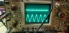
Here's a shot of the oscilloscope with 500Hz fed in. Right channel on top. This is at pin 6 of the outputs of the two replacement op-amp chips.
There's something happening on the right side, but it's not good.
The issue isn't the op-amp(because it doesn't move when I swap the right with the left), or the signal going into the op amp, which is fine on both sides.
Sooooo, now I'm not sure what to do.
There's something happening on the right side, but it's not good.
The issue isn't the op-amp(because it doesn't move when I swap the right with the left), or the signal going into the op amp, which is fine on both sides.
Sooooo, now I'm not sure what to do.
Attachments
klamsoss
Be willing to fail and try again.
@p4spooky I'm ordering some 1n-5404 diodes as they are indicated as a suitable replacement for the SR3AM-8 diodes. These differ from the ones suggested by you in that they are 3A rather than 4 and are still 400V devices. What leads you to suggest increasing the reverse voltage and forward current ratings? I'm not necessarily questioning your advice, I just want to learn the basis for it. Additionally, I have some of the little blue ceramic 10k pF 630V X7R ceramic caps that would seem appropriate to replace the caps bridging D701 through 704.. It seems prudent to replace them at the same time as I replace the diodes.
@sregor do you have any further suggestions?
Now that I have narrowed it down to being unrelated to the TK area, definitely not a problem with either replacement chip, but it's something that is somehow happening IN the chip (presumably due to an affect originating elsewhere, but only on the one channel). Q303 and Q304 are pretty much the only semiconductors in the preamp that I haven't replaced. I'm not seeing how they would impact the issue, though.
Just some thoughts. First, with power off, Ohm out the tone control with the tone buttons in the defeat (out according to schematic) position
The resistances should measure 4.3K left channel 24 to 27 (ground) and right 16 to 20 (ground)
43K left "1" to 24 right "2" to 24
47k left "1" to 27 (ground) right "2" to 20 (ground)
The "1" and "2" are what looks like script numbers on the connections between the treble and the bass controls in the schematics
Of course, you have a good channel and a bad channel so if any difference, investigate connections and even could be issue with switch.
A second test to try - isolate the filter switches by lifting one end of R329 and 330 and test to see if signal comes back. Pins 22 and 18 appear to be the outputs (not a great schematic to read)
FWIW there is a repair thread where there was a short inside one of the switches which was driving people crazy.
392hemirat
New Member
Noob here, I also have an A5 but my problem is the right power section is super weak but not dead completely. I've switched sources, inputs, swapped L to R, repeatedly manipulated all controls/switches, and I have run the known good left preamp channel out into the right main-in. Nothing effects/changes the output in any way. Balance to full right produces output 1/10th that of the left channel. Any ideas? Thanks in advance 

Best to start your own thread.Noob here, I also have an A5 but my problem is the right power section is super weak but not dead completely. I've switched sources, inputs, swapped L to R, repeatedly manipulated all controls/switches, and I have run the known good left preamp channel out into the right main-in. Nothing effects/changes the output in any way. Balance to full right produces output 1/10th that of the left channel. Any ideas? Thanks in advance
392hemirat
New Member
Roger that