• The move to the new server is done. There are some software and database maintenance updates in process. This has us passing the hat around to help out. We appreciate any donations. Seriously, even a dollar helps. The payment page may be found here - https://www.audiokarma.org/support.html

DanWentworth

New Member
This venerable old receiver recently started going into protection mode.
The obvious damage was to R41 ( 5W 0.47Ohm cement by Micron 77).

After reading the post by Jon_Logan, goat67 and str8tlk http://audiokarma.org/forums/index.php?threads/onkyo-tx-8500-trouble.223285/page-5

I determined that Q14 is also toast.
With the Outputs (Q12,Q13,Q14 and Q15) removed I measured the B1 to B2 Voltage (1.136 Vdc) as well as B1 to ground (0.69Vdc)
R29 (47ohm 1Watt) has discoloration and is a candidate for replacement..

The plan is to replace
- The Output Transistors with ON Semi MJ21193\94's (Q12,Q13,Q14 and Q15)
- The Collector and Emmiter Resistors (R39toR46) (0.47Ohm 5Watt Cement, 0.33Ohm 3Watt Cement)
- (R29 and R30)

I am running into a difficult time sourcing the Collector and Emitter resistors. (Currently Micron 77), I have been unable to find specs for these.

Sticking with the same form factor:
My gut tells me that the Collector needs to have the same specs as the Emitter I am seeing temperature coefficients from 600ppm and -80--25ppm.

I welcome any advice\suggestions particularly regarding the Collector and Emitter resistors.

Dan
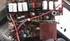


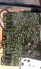
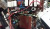
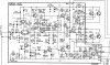
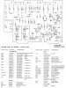
IMAG0484.jpg IMAG0485.jpg IMAG0483.jpg IMAG0486.jpg
 
Register to hide this ad
Can you provide links to the resistors you have questions about, Mouser? Digikey Or?
I would be checking all the transistors out of circuit along with the resistors

Q6 D5 Q7 Q8 Q10 Q9 Q11 Q12 Q14 Q13 Q15
All corresponding emitter resistors

Lower temperature coefficients are better but realistically when this amp was made they probably were not the best.
 
Can you provide links to the resistors you have questions about, Mouser? Digikey Or?
I would be checking all the transistors out of circuit along with the resistors

Q6 D5 Q7 Q8 Q10 Q9 Q11 Q12 Q14 Q13 Q15
All corresponding emitter resistors

Lower temperature coefficients are better but realistically when this amp was made they probably were not the best.
 
My plan is to purchase the known items in preparation for a trip to my friend's who has a proper solder station.
Will remove and test the items out of circuit at his bench.
Does the B1 to B2 voltage and B1 to ground test give a high degree of confidence in the driver circuit? I did these measurements with a calibrated Fluke DVM. Ran the diode tests on the Outputs Q14 was toast. Q12,Q13 and Q15 appear OK. I plan to replace them all as a unit on this channel


The Micron 77's are ~22mm in length

I have a list of Vishay (Combination of 0.33Ohm and 0.47Ohm) they are modern and meet the specs but are different form factor.
https://www.mouser.com/ProjectManag...jectGUID=7378bc3d-58d5-4dbf-81de-428af4efc134
My first choice for the 0.47Ohm was: http://www.mouser.com/ProductDetail...wBHt4sqdPspctxN3bgSZhv60BBu4uDmVOZBz7olqE3Q==
But I do not see an equivalent in 0.33Ohm.

In the IRC's the 0.33Ohm are 5Watt vs 3Watt spec with a 600PPM
http://www.newark.com/international-resistive/caw5r470jlf/resistor-power-wirewound-0-47/dp/40M8199
http://www.newark.com/international-resistive/caw5r330jlf/wirewound-resistor-0-33-ohm-5w/dp/40M8198

Regarding the other elements.
This is what I have so far with Mouser PN a lot of it started with info from your previous post.
C1 10uf 25v LR 647-UKL1E100KDDANA
C3 47uf 16v 647-UPW1C470MDD
C4 47uf 10v 647-UPW1C470MDD
C10 330uf 16v 647-UPW1E331MPD
C17 10uf 63v 647-UPW1J100MDD
C18 10uf 63v 647-UPW1J100MDD

R27 660-MOS1/2CT52R331J
R28 660-MOS1/2CT52R331J
R29 71-RS1A-47-E3
R30 71-RS1A-47-E3
Group1 Spec:2.7Ohm 1Watt Metal
R31 588-41F10RE
R32 588-41F10RE
Group2 Spec:2.7Ohm 1Watt Metal
R33
R34
R35
R36
Group3 Spec:0.47Ohm 5Watt Cement
R39 71-CP0005R4700JE14
R40 71-CP0005R4700JE14
R41 71-CP0005R4700JE14
R42 71-CP0005R4700JE14
Group4 Spec:0.33Ohm 3 Watt Cement
R43
R44
R45
R46

D5 512-1N4148
Q6 755-2SC1740STPQ
Q7 755-2SC1740STPQ

mOD Q8 512-KSA1220AYS
mOD Q9 512-KSC2690AYS
ChkPinOut Q10 512-KSA940TU
ChkPinOut Q11 512-KSC2073TU

Q13 863-MJ21193G
Q15 863-MJ21193G
Q12 863-MJ21194G
Q14 863-MJ21194G
 
If you want to match the originals use the ohmites other wise the Vishay 594 series would be fine,

The voltages b1 to b2 does not seem right. Should be 0

B1 to ground .09 volts high could be ok

Measure all the voltages on this board matching what the schematic says
List as an example
Q2
E +11.74 v
B +12.34 v
C +54.91 v

Q3
E -50.12 v
B -49.33 v
C -30.41 v

B1 B2 +BM etc more info the better

Verify Power supply voltages also

I did not review the other info on the parts list....
 
Back
Top Bottom