• The move to the new server is done. There are some software and database maintenance updates in process. This has us passing the hat around to help out. We appreciate any donations. Seriously, even a dollar helps. The payment page may be found here - https://www.audiokarma.org/support.html

Optonica SM4646 Rebuild

Ed Dumas

Member
I just discovered that an amp I gave to my daughter a few years back is actually quite a gem. It is an Optonica SM4646. Optonica was high end to Sharp like Technics was high end to Panasonic. The SM4646, it turns out, was Optonica's top of the line amp for about 1976/77. Optonica brand did not do so well because Sharp entered the high-end market late, and not enough people knew the name for them to grab enough share of the market to keep the line going. To give you an idea of the build quality, Optonica committed to putting three transformers into this gem, one for each side of the power amp, plus one for the pre-amp portion.

So, I have offered to my daughter to do a re-build on her amp for free to return it back to factory specs. I will put new electrolytic caps, put in a new relay switch, clean all the switches and control pots, replace any bad trim-pots inside, replace the double transistors which tend to go, and adjust back to factory specs. I have a service manual already for it.

Does anyone out there have any experience with Optonica? Are there any perils in this amp that I should watch out for?
 
Register to hide this ad
Nice amp. I had a short look at it, it comes with hybrid power IC's, probably unobtainium if they ever go faulty, so a full rebuild is not a bad idea. Be careful though with adjustments and testing the amp in between stages, you do not want to blow up one of those IC's.

The way it is built reminds me of Pioneer, if they had anything to do with it, then also check for any other questionable transistor (if you post a list of what's inside we can comment).
 
I just discovered that an amp I gave to my daughter a few years back is actually quite a gem. It is an Optonica SM4646. Optonica was high end to Sharp like Technics was high end to Panasonic. The SM4646, it turns out, was Optonica's top of the line amp for about 1976/77. Optonica brand did not do so well because Sharp entered the high-end market late, and not enough people knew the name for them to grab enough share of the market to keep the line going. To give you an idea of the build quality, Optonica committed to putting three transformers into this gem, one for each side of the power amp, plus one for the pre-amp portion.

So, I have offered to my daughter to do a re-build on her amp for free to return it back to factory specs. I will put new electrolytic caps, put in a new relay switch, clean all the switches and control pots, replace any bad trim-pots inside, replace the double transistors which tend to go, and adjust back to factory specs. I have a service manual already for it.

Does anyone out there have any experience with Optonica? Are there any perils in this amp that I should watch out for?

The SM4646 is a gem. I liked it so much I have two. I've never had a problem with them. One is in daily use. I'm sorry I can't add anything as to what to watch out for. I think jeromach is correct on the IC's being unobtainium. I would love to see your progress on the rebuild. If during your rebuild you need anything checked out on a working unit let me know. Good luck!
 
Hi,
The power IC's are Optonica rebranded Sanken S-80W Hybrids. They used to be impossible to find but I know that a bunch of originals recently came into the market.
 
Last edited:
I'd love to see your progress on this as I've got one of these and love it. It is currently working but I'd like to ensure it continues to do so
 
Thanks for the nods of encouragement! The amp is coming back to me in a couple of days, and I will begin it then. It is basically in working condition, but I bet the adjustments are off due to little or nothing being done since it was built. The IC's are fine at this moment, but the plan is to replace electrolytics and anything else that might damage them. I will post some photos as I go along.

My biggest concern at this point is the adjustment procedures do not seem to be too clear in the service manual that I have. The Technics amps that I recently did seem to have a better set of instructions for this. And, yes, I am not going to adjust anything at first, just take some measurements. I will adjust it again after installing new capacitors. If anyone out there knows any more about adjusting this gem, it would be great to hear from you.

Having said that, I think from what I understand in the manual that some of the adjustments on this unit are "automatic adjusting" and therefore taken care of. (Something about push-pull and auto leveling?) I am not sure I understand how that is done electronically, but there was something like that in the manual. When I see the amp in front of me while I read, I will be able to figure out more.
 
Last edited:
The way it is built reminds me of Pioneer, if they had anything to do with it, then also check for any other questionable transistor (if you post a list of what's inside we can comment).

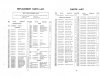
Here is the page 19 of the service manual.

Page 19.jpg

Can you see the transistor part numbers from this page to figure out what is questionable? I know there are some double transistors that are questionable.
 

Attachments

At a quick glance I see no specific transistors known as bad, but I'd replace any of the small signal ones (to-92 case) if they have black/oxidized legs. Same when there is a significant amount of noise with the volume down and/or crackling, either light or more severe.
The larger ones (TO-220 I think) I'd leave in place, but you should check their solder connections, these might have suffered over the years from heating up and cooling down.

And as far as I could quickly see there indeed is nothing to adjust. The way it looks the DC balance at the outputs is performed by the double transistors in the main amp stage, if they still "perform" at least :). But you know how to replace them.
You could measure the DC at the outputs before replacing them, it's always interesting to see how it performs after so much years of service.
 
The way it looks the DC balance at the outputs is performed by the double transistors in the main amp stage, if they still "perform" at least :). But you know how to replace them.

Do you happen to know if the replacements for those double transistors happen to be the same ones I used in the Technics amps? I am pretty sure I can still get matched pairs from what I have left if they are right for the job.
 
Yes, it uses the 2SA798, so you can use matched KSA992's like in the Technics SU-8077.
 
@spark1, Were there any surprises?

I just got mine, and it works well. Just a bit of scratchiness on the balance knob and the 20db attenuator button.

I will go through it with Deoxit when the can arrives.
 
890265-optonica-sm4646-integrated-amp.jpg


http://www.thevintageknob.org/optonica-SM-4646.html
 
Yes, a few surprises. There were a few differences between the components in the service manual and actually on the boards. I am fairly certain that no one had been inside this unit before me, so Optonica apparently made some in-production design changes.

One difference was the power supply caps for the phono board. The manual said 1uf/100V, they were 33uf/80V in my unit. The board was clearly designed for smaller caps, so Optonica had to "shoehorn" them in. I ended up going with 33uf/63V replacements, as the circuit measured only about 43V. While still a bit tight, these fit onto the board much better.

I would recommend you build up your parts order based on a physical examination of the boards, rather than using the manual. Also, note that on the power amp board, there are a couple of caps that are neither numbered nor marked for polarity. So, you will need to be careful with these to note polarity before removal. This was especially interesting, because overall Optonica did a superior job with providing part numbering and pin-out info on the boards...for the most part, this info is on both the top-side and foil side (a rarity, in my experience).

Also, be aware that the power supply and protection circuits are distributed across multiple boards (a consideration in choosing series of capacitors to use). The part numbering scheme will tell you the functional section to which part is attached (for example, protection circuit is 5xx series, power supply is 6xx, power amp is 4xx, etc).

Boards were not overly difficult to access. For the top two boards, you will need to remove the nuts and screws that attach the switches/pots to the front of the chassis (after removing the faceplate, of course). Then you can pull the shafts in thru the chassis and flip the boards upward, allowing you to get to the boards below. The lower boards can remain in place, as can the main amp board.

The only transistors I replaced were the differential pairs (2SA798s)...used a pair of 2SA992s to replace each 2SA798 (matched for Vbe and hFE, and thermally coupled with shrinkwrap. DC offset was 36mV in one channel and 48mV in the other with the 2SA798...not bad, but replacement is easy and with the 992s it dropped to 9mV and 14mV, respectively.

EDIT: In the pic posted by BigElCat above, you can see the pair of blue 33uf/80V caps on the EQ board at the lower right...the one on the right is almost laying over flat to allow them to both fit. I think you could even use 50V replacements there for a perfect fit, but I wanted to leave more of a margin so went with 63v.

Also, while I used to use D5 on pots, followed by Faderlube (or whatever Caig calls it now), I tend to now use Faderlube only. That's what I did on the 4646. D5 on the switches and selectors. YMMV.

EDIT #2: I don't know your level of experience, so this may be something you already know...but I would strongly recommend that you build a DBT and use it to help assure no problems after finishing each board (or even each half of a board).
 
Last edited:
Back
Top Bottom