• The move to the new server is done. There are some software and database maintenance updates in process. This has us passing the hat around to help out. We appreciate any donations. Seriously, even a dollar helps. The payment page may be found here - https://www.audiokarma.org/support.html

output transformer for a heathkit w5m

Steve -- When I measured my own 458 transformers many years ago, I too came up with a similar primary impedance result at just shy of 9.5K A-A, with screen taps at 50% of the winding. This was measured using the full 16 Ohm secondary winding to ensure absolute accuracy.

As general information for those who may question this transformer's 9 Ohm tap, it will be found that the "8 Ohm" tap on most OPTs with a 16 Ohm full secondary winding will rarely equal exactly 8 Ohms (it can be slightly high or low), due to the limitations of where the actual tap can physically be connected to the secondary winding. However, it is always customarily designated as an 8 Ohm tap anyway, since that is the intended tap impedance, even if it's only close. The 4 Ohm tap will always be spot on however, since that tap is placed at exactly 50% of the winding, a point which is readily accessible within the build of the coil form .

Finally, I also concur that Atwood's information is, ah, interesting (yeah, that's the ticket)! :)

Dave
 
I may be wrong, but I thought impedance was measured at 1000 Hz, which may explain the differences.
 
A decent transformer such as what's under discussion here should have no issues with a range of frequencies say from 50Hz to maybe 4 or 5KHz. With a transformer of unknown use or quality, I find 400Hz useful. IME, the real frequency limitation lies with the meter: a lot of the lower cost units specify accuracy at power frequencies of just 50-400Hz. 1KHz may be well beyond meter's design spec...unless of course it's a decent meter of known capabilities. Plus, 60Hz is obviously convenient.

Regarding 9 ohms vs 8 ohms, not sure of the mechanical winding implications but with 16-9-4 the turns ratios are 4-3-2. If 8 ohms the ratios are 4-2.83-2. While 9 vs 8 may be an issue during design phase of an amp, practically speaking it's a curiousity: no speaker is exactly 8 ohms.
 
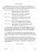
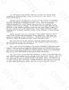
As a followup to last week's discussion, I was able to get my scanner working as well as image editing software so here are the four pages of the 1966 Heath W5 service bulletin. I was hoping to do higher rez PNGs but due due to AK file size limitations, they're JPGs. Rez should be good enough for most uses.


W5_Ser_1.jpg W5_Ser_2.jpg W5_Ser_3.jpg W5_Ser_4.jpg
 
Thanks for scanning and posting Steve - very interesting to appreciate how they advised service people. Always a good idea to look out for charred resistors and bulging capacitors !

In the surgistor instructions, it says to monitor the voltage at G, but I can't make out the next word - can you decipher that?

Ciao, Tim

I have no problems, it reads: "half moon"

The different (up to 4) sections of multi-section can-type electrolytic caps were usually identified by a geometric shaped cut out in the phenolic insulator at the solder tags bottom which can be : square, triangular, half moon or none. The same geometric symbols were then used on the schematic as a reference for identification purposes.

Bimetal type "surgistors" are no longer manufactured but you can replace it with a NTC inrush current limiter resistor . As the suggested surgistor has a cold (open) resistance of 100 ohms, a CL-90 would be the closest substitute but I'm not sure its current ratings (2A) will be enough for this application.
 
Last edited:
I have no problems, it reads: "half moon"

The different (up to 4) sections of multi-section can-type electrolytic caps were usually identified by a geometric shaped cut out in the phenolic insulator at the solder tags bottom which can be : square, triangular, half moon or none. The same geometric symbols were then used on the schematic as a reference for identification purposes.

Bimetal type "surgistors" are no longer manufactured but you can replace it with a NTC inrush current limiter resistor . As the suggested surgistor has a cold (open) resistance of 100 ohms, a CL-90 would be the closest substitute but I'm not sure its current ratings (2A) will be enough for this application.

I've used the CL90 in the W5s I've refurbished w/o issue. Actually, I've never had a PT failure in a W5 (or W3) w/CL90 installed. Luck or causation...who knows?
 
Bimetal type "surgistors" are no longer manufactured but you can replace it with a NTC inrush current limiter resistor . As the suggested surgistor has a cold (open) resistance of 100 ohms, a CL-90 would be the closest substitute but I'm not sure its current ratings (2A) will be enough for this application.
The CL-80 should be good enough for this application. The cold resistance is not quite as high at 47 ohms vs. 120 ohms for the CL-90, but the current rating is greater at 3A vs. the CL-90's 2A rating, with maximum capacitance @ 120V identical between both models. Also, the CL-80 resistance under max current is less than half that of the CL-90, so it's effect on the amp performance is lessened.
 
The CL-80 should be good enough for this application. The cold resistance is not quite as high at 47 ohms vs. 120 ohms for the CL-90, but the current rating is greater at 3A vs. the CL-90's 2A rating, with maximum capacitance @ 120V identical between both models. Also, the CL-80 resistance under max current is less than half that of the CL-90, so it's effect on the amp performance is lessened.

I doubt the maximum current rating of either makes much different in the choice for a typical tube amp. Are high power amp would be a different story and you would need to do the calculation. If you use the formula on the CL data sheet to calc the resistance for a specific load they aren't too much different but the higher cold resistance of the CL-90 makes for better inrush limiting. I used an arbitrary 500mA for primary quiescent current (pick your own value for the formula). At 500mA the CL-80 was about 5 ohms and the CL-90 was about 7.8. The difference in voltage drop at 500mA is approx 2.5 vs 4 volts. If your line voltage is high the CL-90 might be a better choice depending on the actual primary voltage rating of your power transformer.

John
 
Regarding 9 ohms vs 8 ohms, not sure of the mechanical winding implications but with 16-9-4 the turns ratios are 4-3-2. If 8 ohms the ratios are 4-2.83-2. While 9 vs 8 may be an issue during design phase of an amp, practically speaking it's a curiousity: no speaker is exactly 8 ohms.

Early Peerless stuff was 2, 4, 8, 16R, and the later( like S258Q ) were 1, 4, 9, 16R. The secondary config being two CT 4R coils. The Earlier 20-20Plus S256Q was 2, 4, 8, and the later S258 was a 1, 4, 9...
cheers,
Douglas
 
Back
Top Bottom