• The move to the new server is done. There are some software and database maintenance updates in process. This has us passing the hat around to help out. We appreciate any donations. Seriously, even a dollar helps. The payment page may be found here - https://www.audiokarma.org/support.html

Output Transformer Primary Questions

FlaCharlie

Super Member
So I'm thinking about trying either some Russian 4P1L (a directly heated pentode) or its cousin the 12P17L (an indirectly heated pentode) in PP and I'm trying to get an idea of what OT primary value would be most suitable.

I know tubes are fairly forgiving when it comes to differences in load but I'd like to see if I have anything in my junkbox that's in the ballpark.

The 4P1L is quite popular wired as a triode and is typically used in PSE (parallel single-ended) configurations using OTs with ~3k primaries.

So, two questions:

What primary would be suitable for PP with tubes wired as pentodes?

What primary would be suitable for PP with tubes wired as triodes?

Here's the data sheet for the 4P1L, which is the third tube listed. It seems that footnotes 1, 2 and 3 apply and that in Class A1 (a single tube in, I assume, pentode) the tube produces 1.5w with a 6k load and 2.6w with a 7k load. But there's no info on PP operation.

4P1L Data.jpg

The data sheet for the 12P17L doesn't seem to list any info regarding proper loads or power output.

I know that the load in PSE should be half of the SE load. I assume that PP load will be higher than SE but how much higher? Double?
 
Register to hide this ad
Some good info here.
https://www.bartola.co.uk/valves/2012/06/29/4п1л4p1l-triode-curves/

Looks to me like 8k to 10k primary for push pull should work well. A good EL84 output transformer would likely be a reasonable candidate. My preference would be to stay with a class A operating point and no global feedback. You will need a good speaker match as you won't have a lot of power, probably around 5 watts. It should sound nice.

You might find some useful info in this thread.
https://www.diyaudio.com/forums/tubes-valves/304155-4p1l-pp-feedback-help.html

John
 
Looks to me like 8k to 10k primary for push pull should work well. A good EL84 output transformer would likely be a reasonable candidate. My preference would be to stay with a class A operating point and no global feedback. You will need a good speaker match as you won't have a lot of power, probably around 5 watts. It should sound nice.
Thanks . . . would 8k to 10k be for pentode or triode? Or would it work for either one?

I get confused with classes of operation. What operating points would be required to stay in Class A? Triode operation, or can it also be pentode?

I've been on a junkbox OT testing binge and I think the closest I've found so far are some PP OTs that were originally used with 6GW8s. They're about 7.2k : 8 ohms but they're pretty small.
 
I think the 8k-10k would be for triode connection. The Bartola link above is mainly related to triode useage of the tube.
 
I think the 8k-10k would be for triode connection. The Bartola link above is mainly related to triode useage of the tube.
Yeah, everyone seems to run the 4P1L in triode. They are very linear in triode. I'd like to at least try them in pentode, though.

Any suggestions for PP pentode? Should the load be higher?

I'm thinking I might drop them into a Magnavox 8801 chassis. The stock OTs are listed as 6k into 4 ohms in the Sams, so that would be 12k into 8 ohms. I figured that might be too high, though.

I'm just curious at this point so I don't plan on buying transformers. I already have the tubes and loctal sockets. I figure if it doesn't work out I can always use 7C5s or 14C5s (loctal base 6V6s), which I also have.
 
Quite often pentodes use a lower impedance than triodes but it depends on the B+ and the screen voltage. You can adjust screen voltage to make them work with higher impedance transformers.
 
Quite often pentodes use a lower impedance than triodes but it depends on the B+ and the screen voltage. You can adjust screen voltage to make them work with higher impedance transformers.
Is there a predictable relationship between screen voltage and load impedance? Such as lower screen voltage if you want to use higher impedance or vice versa?

Or some measurement that would indicate how much the "ideal" load is affected by the changes?

If so, it would have to be a simple measurement since I don't have a scope.

I do have plenty of duct tape, though.;)
 
In many American tube data sheets for pentodes there is a graph showing where the zero grid volt curves will be for differing screen voltages. You can use that to draw a load line to best fit a certain impedance value.
 
In many American tube data sheets for pentodes there is a graph showing where the zero grid volt curves will be for differing screen voltages. You can use that to draw a load line to best fit a certain impedance value.
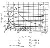
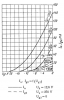
Unfortunately, the data sheets for these tubes have relatively little info. These are the only graphs available. They seem to be same for both tubes.

I've only drawn load lines a few times but, in all cases, the tubes were triodes used for preamp duty. Those graphs looked quite different from these.

Although many people run these tubes at higher levels than the 7.5w max plate dissipation shown, I was planning on sticking pretty close to the limit - probably around 250v - 260v on the plate and - 9v to - 9.5v on the grid (possibly using a 9v lithium battery).

Those operating points would seem to indicate a combined plate / screen current of ~25mA and a screen voltage of ~150v - 160v.

Based on those operating points and the graphs, can you offer any insights regarding the preferred OT primary? Or how a higher or lower screen voltage would affect that?
12P17L Graph 1.png
12P17L Graph 2.png
 
The Japanese schematic in one of the threads linked above is the only example I've seen where these tubes are being run PP in pentode mode. It uses OTs with 8K primaries.

I've seen it before but somehow it doesn't make sense to me since the data sheet seems to suggest using a 7k primary in a SE design. I would expect there to be more of a difference.

I recall, years ago, being interested in a PP design that used 47s, which are also directly heated pentodes like the 4P1L. The data sheet for the 47 specified a 7k primary for SE but it also gave no data for PP operation. The designer, Gary Pimm, figured they would want to see a 14k load in PP. I believe he used some Fisher OTs and ran 8 ohm speakers on the 4 ohm tap in order to get somewhat close to a 14k load.

Does that make sense or is there some flaw in that approach that I'm missing?
 
Unfortunately, the data sheets for these tubes have relatively little info. These are the only graphs available. They seem to be same for both tubes.

I've only drawn load lines a few times but, in all cases, the tubes were triodes used for preamp duty. Those graphs looked quite different from these.

Although many people run these tubes at higher levels than the 7.5w max plate dissipation shown, I was planning on sticking pretty close to the limit - probably around 250v - 260v on the plate and - 9v to - 9.5v on the grid (possibly using a 9v lithium battery).

Those operating points would seem to indicate a combined plate / screen current of ~25mA and a screen voltage of ~150v - 160v.

Based on those operating points and the graphs, can you offer any insights regarding the preferred OT primary? Or how a higher or lower screen voltage would affect that?
View attachment 1999083
View attachment 1999086

For those curves, a plate and g2 voltage around 150V, and idle current about 45 mA with a 2k a-a load looks pretty good. The 1k, SE load line is based on a 45-degree diagonal. one block up and one block over. 20V/20 mA is 1kOhm...double for Class A PP.
cheers,
Douglas
 
For those curves, a plate and g2 voltage around 150V, and idle current about 45 mA with a 2k a-a load looks pretty good. The 1k, SE load line is based on a 45-degree diagonal. one block up and one block over. 20V/20 mA is 1kOhm...double for Class A PP.
cheers,
Douglas
I see that an operating point of 150v and 45mA results in plate dissipation that's just under the 7.5w max. But you've lost me when it comes to determining the load for that operating point.

Could you explain further how you determine the loads?

The data sheet I posted earlier seems to suggest either a 6k or 7k load with the tube run SE in, I assume, pentode mode. Did I misinterpret those footnotes on the data sheet?

The guys who run these PSE in triode use 3k primaries and operating points around 250v and 30 to 35mA.

I don't think I've ever seen a PP OT with a 2k primary and I'm sure I don't have anything like that in my parts bin.

It is easy, draw the line. From the idle point, use a divider and see how linear it is...and if it ever goes above the max power line.

Douglas
 
It is easy, draw the line. From the idle point, use a divider and see how linear it is...and if it ever goes above the max power line.

Douglas
You've lost me. I'm apparently even more of a simpleton than I thought.

I'll try to find a basic, step by step, explanation of how to draw a load line for output tubes. I've done them for preamp tubes that are resistively loaded but these charts look very different and they obviously require a different procedure. I'll look for the "For Dummies" version.

But, in the meantime . . .

Footnote #2 in the data sheet that I posted seems to suggest a Class A operating point using a 7k primary with 240v on the plate, 160v on G2 and - 10.2v on G1. This produces 2.6 w.

Going back to your earlier statement that a PP configuration would require 2x the primary impedance of a SE OT . . . wouldn't that indicate a PP OT with a 14k primary?

This would also agree with the example I gave re: Gary Pimm's PP 47 amp.

Footnote #1 in the data sheet suggests Class A operating points that are essentially the same as what you have suggested: 150v on the plate, 150v on G2, -7v on G1. It says to use a 6k primary with these operating points and that this produces 1.5 w.

So wouldn't this indicate the use of a 12k PP OT with those operating points?
 
Draw both load lines( the 6k and the 1k ) and post the picture. The usual thing is to double the SE load for PP. This works as long as you STAY CLASS A. If you go into an AB design, it gets more interesting... :)
cheers,
Douglas
 
Draw both load lines( the 6k and the 1k ) and post the picture. The usual thing is to double the SE load for PP. This works as long as you STAY CLASS A. If you go into an AB design, it gets more interesting... :)
cheers,
Douglas
Well, as I said, I don't know how to draw load lines for output tubes. I need to find a step by step, "for dummies", tutorial somewhere. I'm obviously not very technically astute.

Perhaps you could post a picture comparing the 6k and 1k lines and explain the advantages / disadvantages of each.

Not surprisingly, I'm also not real clear on the differences between Class A and AB. I know that SE is always Class A and that PP can be but is usually AB, and that Class A runs at full dissipation at all times, but that's about the extent of my knowledge.

From a practical (rather than theoretical) point of view, what does it take to keep the tubes in a PP amp running in Class A?

And, if the amp was designed to run in AB, how would that affect the OT primary? Would it be more or less than 2x the SE load?

Thanks for your input on this.
 
Tutorial:
https://robrobinette.com/Drawing_Tube_Load_Lines.htm
I haven't read the entire page but mightbe a good start
Almost all of that link deals with load lines for resistively loaded 12AX7s. At the very end there's a small section that uses the PP 6V6 output stage of a Fender Deluxe as an example.

That amp is Class AB and the focus is on how to determine the overall maximum power output of the amp, the maximum power produced when it's operating in Class A and the maximum wattage in Class B.

I did draw some lines using the info. I guess I need to look at load lines for several different operating points based on the OTs I have. I haven't decided if I will proceed with this project but, even if I do, I won't be buying any transformers. It's a junkbox project and I'll probably use a Magnavox console chassis.

The OTs I have are 6.5k : 4 ohms, 7.2k : 8 ohms and 7.75k : 4 ohms. Obviously, the 7.2k could use 4 ohms for a 3.6k primary. I do have a couple of 4 ohm setups but I'd prefer not to be limited to using them.

BTW, the stock Magnavox 88xx OTs, which are listed in the Sams as 6k : 4 ohms are the ones that actually measure 7.75k : 4 ohms.

So I have some questions about the wattages obtained from the calculations.

I did one for a 7k OT with operating point of 250v plate, ~23 mA. It indicated maximum power in Class A of ~2.94w and maximum in Class B as ~7.66w.

Question #1: Does this mean that the overall maximum power output (disregarding distortion levels) is 7.66w and that the first 2.94w are in Class A and that anything above that are Class B?

OR . . . are the wattages additive? So that the the overall maximum power output is 10.6w?

It seems that the overall maximum wattage is the maximum in class Class B but then I also drew lines based on the 2k OT and operating points Douglas @PakProtector suggested, 150v plate, 45mA.

That's when I got confused.

It indicated maximum power in Class A of ~4.02w and maximum in Class B as ~2.47w.

Question #2: Assuming I've done it correctly, does this mean that the overall maximum power output drops when it transitions into Class B?

OR . . . if the wattages are additive, that the overall maximum power output is 6.49w with the tubes spending more time running in Class A?

Question #3: Is there some advantage to choosing operating points that result in higher Class A output rather than higher Class B output?

If yes . . . what does it take to keep the tubes in a PP amp running in Class A?
 
Last edited:
Almost all of that link deals with load lines for resistively loaded 12AX7s. At the very end there's a small section that uses the PP 6V6 output stage of a Fender Deluxe as an example.

That amp is Class AB and the focus is on how to determine the overall maximum power output of the amp, the maximum power produced when it's operating in Class A and the maximum wattage in Class B.

I did draw some lines using the info. I guess I need to look at load lines for several different operating points based on the OTs I have. I haven't decided if I will proceed with this project but, even if I do, I won't be buying any transformers. It's a junkbox project and I'll probably use a Magnavox console chassis.

The OTs I have are 6.5k : 4 ohms, 7.2k : 8 ohms and 7.75k : 4 ohms. Obviously, the 7.2k could use 4 ohms for a 3.6k primary. I do have a couple of 4 ohm setups but I'd prefer not to be limited to using them.

BTW, the stock Magnavox 88xx OTs, which are listed in the Sams as 6k : 4 ohms are the ones that actually measure 7.75k : 4 ohms.

So I have some questions about the wattages obtained from the calculations.

I did one for a 7k OT with operating point of 250v plate, ~23 mA. It indicated maximum power in Class A of ~2.94w and maximum in Class B as ~7.66w.

Question #1: Does this mean that the overall maximum power output (disregarding distortion levels) is 7.66w and that the first 2.94w are in Class A and that anything above that are Class B?

OR . . . are the wattages additive? So that the the overall maximum power output is 10.6w?

It seems that the overall maximum wattage is the maximum in class Class B but then I also drew lines based on the 2k OT and operating points Douglas @PakProtector suggested, 150v plate, 45mA.

That's when I got confused.

It indicated maximum power in Class A of ~4.02w and maximum in Class B as ~2.47w.

Question #2: Assuming I've done it correctly, does this mean that the overall maximum power output drops when it transitions into Class B?

OR . . . if the wattages are additive, that the overall maximum power output is 6.49w with the tubes spending more time running in Class A?

Question #3: Is there some advantage to choosing operating points that result in higher Class A output rather than higher Class B output?

If yes . . . what does it take to keep the tubes in a PP amp running in Class A?
Anyone?
 
When drawing load lines, you basically have two lines, one Class-A line, and one steeper Class-B line (and than mirrored obviously for a full sine wave).
I think the easiest explanation of this, can be found on Merlin Blencowe's website; http://www.valvewizard.co.uk/pp.html
So your Class-A power is up till the point the other graph line goes up into Class-B mode, the "kink" in the graph

The maximum output power is just the (maximum) RMS voltage times RMS current P = V * I (or P = E * I, depending where you walk around on this planet)
The RMS voltage is HT-Vmin / 1.41.
HT is the total anode-cathode voltage, Vmin is the voltage at the Vg = 0V line.
The RMS current is; Ipeak (at Vg=0V) / 1.41

So P = Vrms * Irms = ((HT-Vmin) / 1.41) * (Ipeak / 1.41) = (HT-Vmin) * Ipeak / 2.
With the same formula you can calculate the Class-A power.
So before the "kink" in the graph, were now Vmin is the transition point in the graph

A (major) downside of running in Class-A is that things will draw a constant current all the time.
Which means that things get HOT very quickly.
So that is something to keep in mind when choosing which tubes you want to use, don't go for small tubes like EL90/6AQ5, but go for a big sturdy 6V6 for example.

Practically speaking; to run your design more into Class-A mode, just lower the HT voltage somewhat, get an higher primary impedance, and use an higher bias current.
 
Back
Top Bottom