• The move to the new server is done. There are some software and database maintenance updates in process. This has us passing the hat around to help out. We appreciate any donations. Seriously, even a dollar helps. The payment page may be found here - https://www.audiokarma.org/support.html

Over protective Yamaha M-70

JonLewis

AK Subscriber
Subscriber
Picked up a nice exterior condition M70, but in protection mode.

I need to go through the M-70 threads and get my bearings, but this unit will be familiar to some already.

First step was trying the DBT to verify protection. Consistent bright150w bulb, no clicks heard from the relays.

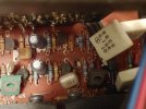
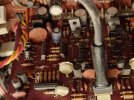
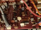
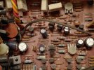
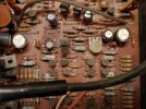
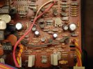
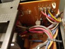
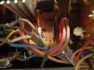
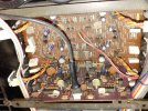
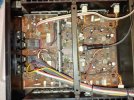
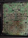
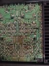
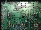
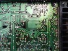
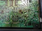
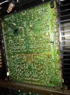
I'm pretty new, but I do not see anything to indicate past work and nothing looks overtly wrong, except for the angry red protection light.
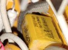
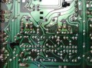
20240622_144829.jpg

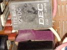
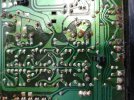
20240622_144415.jpg

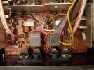
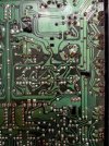
20240622_144503.jpg

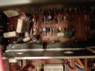
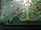
20240622_144632.jpg
 
Register to hide this ad
Removed and checked the two glass fuses- OK.

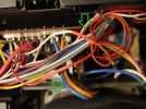
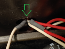
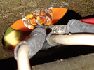
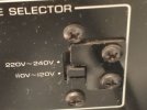
Oh! found some past work evidence.

Power switch.
20240622_154900.png

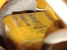
Not sure what this is about.
20240622_154924_HDR.png

1719087013318.png
 
Last edited:
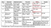
Looking at the service manual I skipped steps 1 and 2 for now as I have one meter.

DC offset:
Lch TPO to TPE ~ -4
Rch TO to TPE ~ -14

I'm confused why there are two sets of pins (on each channel side), is this speaker sets A + B?

I tried the schematic but I'm not there yet.

1719096726461.png

Back to steps 1 AND 2, just test, no adjust:

-B power supply: 65.8v
Photo coupler: 2.2v
 
Last edited:
The left green square is for idling current adjustment AND DC offset adjustment. For DC offset adjustment, positive probe to TPO and negative probe to chassis ground. USE mini grabbers or IC grabbers, do not use test leads for this under any circumstances.

For idling current adjustment, positive probe to TPO and negative probe to TPE. If you measure a negative voltage, use the absolute value (positive value) of the measurement. Again, use mini grabber, not bare test leads.
 
The left green square is for idling current adjustment AND DC offset adjustment. For DC offset adjustment, positive probe to TPO and negative probe to chassis ground. USE mini grabbers or IC grabbers, do not use test leads for this under any circumstances.

For idling current adjustment, positive probe to TPO and negative probe to TPE. If you measure a negative voltage, use the absolute value (positive value) of the measurement. Again, use mini grabber, not bare test leads.
Man you knew. I need grabbers or I'll be hating myself at some point. I was not attempting to adjust, just get a starting value.
 
I’d measure and adjust the supply rails, Idling current, and DC offset voltage in that order to establish a reference point.
65V is kind of low based on what’s in the SM. Also your photocoupler is out of spec, it should read 1.2V ±0.1V.
Making these adjustments ’might’ actually bring this out of protection … ‘might’.


4256AF8E-77C3-4A64-8180-2BE47C2F16C1.jpeg
 
I’d measure and adjust the supply rails, Idling current, and DC offset voltage in that order to establish a reference point.
65V is kind of low based on what’s in the SM. Also your photocoupler is out of spec, it should read 1.2V ±0.1V.
Making these adjustments ’might’ actually bring this out of protection … ‘might’.


View attachment 3233218
Thanks for the positive thoughts.

I'll work on having dual meters and mini grabbers to continue.

And I'll do some careful dusting. Does not look as bad in person.
 
Brushed and sucked the board component sides.

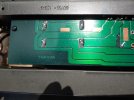
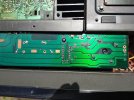
Took the bottom cover off and started to use IPA to cleaned the solder side of the main board.

Grabbers arrived,

2nd multimeter arrived.

Tried to complete step 1 and 2 at the same but found the adjusters had a pretty minor rotation either way and there was no way to put either value where it is suppose to be.

One odd thing is the DBT was out when powering the unit but also the unit did not appear to power. Then it did. Then it didn't.

I tapped the relays and the unit came up in protection and the bulb glowed. Not sure its the relays, or a solder issue, or what.

Wondering if I should open the relays and try to inspect/clean or order new ones?
 
Last edited:
Tried to complete step 1 and 2 at the same but found the adjusters had a pretty minor rotation either way and there was no way to put either value where it is suppose to be.

One odd thing is the DBT was out when powering the unit but also the unit did not appear to power.
Try adjusting it on straight mains without the DBT. DBT does not play well with X-power supply models. <---- M-50, M-70 are a couple x-power supply models..
 
Last edited:
Skipped the DBT and I was able to adjust the power supply and photo coupler with better results.

Protect still on.

Cycled power, protect still on.
 
Tapping may be the relay(s) or something on the board. I'll let it sit for a while, then power it on again, and see what happens.
I’d take the time and reflow all the solder joints including the RCA connectors. I have a B-50 (Japanese version of M-50) and doing that has solved/prevented many issues for me. Tapping is probably helping some cold solder joints make contact. Are you able to upload hi-res image(s) of the solder side of the board?
 
Before I started to clean up a bit, there was what appeared to be an "X" in wax/grease pencil with a blob from the tip. No idea what that is for.

1719768329771.jpeg
 
Last edited:
Back
Top Bottom