• The move to the new server is done. There are some software and database maintenance updates in process. This has us passing the hat around to help out. We appreciate any donations. Seriously, even a dollar helps. The payment page may be found here - https://www.audiokarma.org/support.html

Over protective Yamaha M-70

Thank you for taking the time uploading the images. The solder joints look generally clean from these images, although the board does need a good clean up to get rid of all that flux. Acetone and a light brush will do the job. You may want to examine/reflow some of the lightly burned areas (middle section resistors, etc.)

Have you adjusted the idle current and the DC offset voltages per SM after setting the power supply Yet? They may be off given how far off the photocoupler actually was.
 
Thank you for taking the time uploading the images. The solder joints look generally clean from these images, although the board does need a good clean up to get rid of all that flux. Acetone and a light brush will do the job. You may want to examine/reflow some of the lightly burned areas (middle section resistors, etc.)

Have you adjusted the idle current and the DC offset voltages per SM after setting the power supply Yet? They may be off given how far off the photocoupler actually was.
Yes, I was able to dial them in to spec (at the same time) and that did not cause it to come out of protect mode, even after a power cycle,

Where the board is clean, I did that with IPA. Tough going to get it gone.
 
Last edited:
Looks like new lamps installed to me.
That’s probably it. I, very recently (last week), had to re-solder the protection lamp (B-50) wire to its post, it had completely separated. In the process, the power lamp wire separated from the lamp, so had to change that too, I remember this wiring post assembly well. Still worth checking the wiring to make everything went where it was supposed to. You never know …
 
Are Tr121 and 122 (2sc2240) properly attached to the heatsinks and working? I can see one of them in the photos but not the other one though I doubt that’s the problem right now. If all the adjustments are done properly, I’d have to wonder about the relays themselves.
 
Last edited:
Right, most common reason for protection is blown output transistors from my experience.
That’s correct but the OP mentioned in post #22 that he was able to adjust idle current and DC offset to spec. I doubt that’d be possible with a blown output. Worth a check definitely anyway.
 
The main amp board looks just like the M-50 board just with more components. But definitely looks like it has been messed with after the factory.
 
That’s correct but the OP mentioned in post #22 that he was able to adjust idle current and DC offset to spec. I doubt that’d be possible with a blown output. Worth a check definitely anyway.
Not DC offset, I don't think he is able to get the relays to connect. Avionic asked to measure DC somewhere before the relays, I don't think we got that info.
 
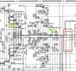
@Asmodeus2112 , you may be right, I haven’t followed this very closely. Per M-70 SM, you can measure the DC offset voltages at the speaker terminals for which you need the relays to come out of protection first, or, between the test point TPO and ground (see below, I think this is what @avionic was asking for) for which you should turn the relays off first (front panel switch). TPO is before the relay so it doesn’t matter if the relay doesn’t come out of protection. I’m not sure which method the OP had used when he said:
Yes, I was able to dial them in to spec (at the same time) and that did not cause it to come out of protect mode, even after a power cycle,

I think we need clearer data on this.

43A2EAC7-413B-4BEA-BF65-4D0FD764EEFB.jpeg
 
Sorry I was away in another state.

I just got two new relays and a replacement for the larger RIFA (from Mouser) to have that ready to change out (when the time is right)).

So the intermittent issue of the power switch working and then not working is now constantly not working. This seemed to come and go after moving the unit around and possibly starting to clean the flux off the solder side, but now its seems to be a full time condition.

Prior to that I had only completed the first two steps and reported out on those only.

In that conversation it was suggested I do flux clean up and re-solder the main board.
1721595523073.png
 
Last edited:
Prior to that I had only completed the first two steps and reported out on those only.
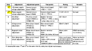
Using two multimeters? See the * Accomplish steps 1* and 2* at the same time by using two digital multimeters.

These two adjustments interreact with each other.
 
Using two multimeters? See the * Accomplish steps 1* and 2* at the same time by using two digital multimeters.

These two adjustments interreact with each other.
Yes, at the same time, as I reported at the time.
Brushed and sucked the board component sides.

Took the bottom cover off and started to use IPA to cleaned the solder side of the main board.

Grabbers arrived,

2nd multimeter arrived.

Tried to complete step 1 and 2 at the same but found the adjusters had a pretty minor rotation either way and there was no way to put either value where it is suppose to be.

One odd thing is the DBT was out when powering the unit but also the unit did not appear to power. Then it did. Then it didn't.

I tapped the relays and the unit came up in protection and the bulb glowed. Not sure its the relays, or a solder issue, or what.

Wondering if I should open the relays and try to inspect/clean or order new ones?
Removed DBT per advice. Then...
Yes, I was able to dial them in to spec (at the same time) and that did not cause it to come out of protect mode, even after a power cycle,

Where the board is clean, I did that with IPA. Tough going to get it gone.
 
I saw this thread on power buttons and testing the power cord for Ohms. https://audiokarma.org/forums/index...0-power-amplifier-broken-power-switch.828418/

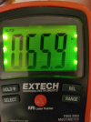
I get 58.9 kΩ. or toggling the switch 0.L. Not sure what that means yet. Beyond the switch seems to be working.

No lights on amp when plugged in (prior was power and protect).

Will check the bulbs.

View attachment 3257893
Again, things seemed to take a step backwards, for whatever reason.

From power as well as protection buttons lit, to all dark.

I've been trying to try to understand schematics, oi.

I know the house wall plug works, but tested it 120v AC. Sometimes you just are better of verifying.
The two wires at front power switch get AC power across the two wires, blue and white (or no power) depending on the button position. The switch operation feels mushy to me, but the state is changing.
I get AC power to the rear external accessory plug.
Rechecked all the glass fuses, they are fine.
Traced the front power button incandescent bulb's red and white wires to their posts and did not get any power there, so its not the bulb (arrived with a past replacement and was working).
 
Traced the front power button incandescent bulb's red and white wires to their posts and did not get any power there, so its not the bulb (arrived with a past replacement and was working).
The power lamp’s driving voltage comes directly from Tr701e (~12Vdc). Please check that first and if nothing, trace back to see where the problem starts.
 
Back
Top Bottom