• The move to the new server is done. There are some software and database maintenance updates in process. This has us passing the hat around to help out. We appreciate any donations. Seriously, even a dollar helps. The payment page may be found here - https://www.audiokarma.org/support.html

PA0016 chips in year 2020

bbtv

Member
I've got a Pioneer M90 which of course needs the PA0016 chips replaced.... former tinkering apparently. At any rate, there appear to be some still on Ebay, but prices are all over the place, and some of the chips terrify me in that they are probably fakes.

Does anyone have recent experience with these? The cost is the cost... if I've got to pay $20 each, so be it. But if the $7 ones from China work, I can wait a month to get them. I suppose the obvious question to ask is, have there been, or are there now, any chips to replace them? I think perhaps a DM7450 "modified" might work but .... I don't really want to go that route.

I'd like to NOT have to make one from discrete components if possible, but I may consider that using one of the SMT to DIP adapters and SMT components. LAST RESORT.

Help! :)
 
Last edited:
Register to hide this ad
I've got a Pioneer M90 which of course needs the PA0016 chips replaced.... former tinkering apparently. At any rate, there appear to be some still on Ebay, but prices are all over the place, and some of the chips terrify me in that they are probably fakes.

Does anyone have recent experience with these? The cost is the cost... if I've got to pay $20 each, so be it. But if the $7 ones from China work, I can wait a month to get them. I suppose the obvious question to ask is, have there been, or are there now, any chips to replace them? I think perhaps a DM7450 "modified" might work but .... I don't really want to go that route.

I'd like to NOT have to make one from discrete components if possible, but I may consider that using one of the SMT to DIP adapters and SMT components. LAST RESORT.

Help! :)

What did you end up doing?
I have an A-77X and con't really figure out how to test them. I've seen prices all over the place as well as origins.
 
The simplest way to test them is to swap the one from the good channel into the bad channel. If both channels are out, then you'll have to do some deeper troubleshooting. Being a DC coupled output stage with feedback, it's not exactly straightforward, so hopefully you've got at least one good channel. If you are certain that the output stages are OK, then look at inputs on pin 14 and 8, and outputs on pin 13 and 9. That's oversimplified but a place to start. I found the internal schematic for the chip online somewhere....that might help you to see how it's supposed to work.
 
The simplest way to test them is to swap the one from the good channel into the bad channel. If both channels are out, then you'll have to do some deeper troubleshooting. Being a DC coupled output stage with feedback, it's not exactly straightforward, so hopefully you've got at least one good channel. If you are certain that the output stages are OK, then look at inputs on pin 14 and 8, and outputs on pin 13 and 9. That's oversimplified but a place to start. I found the internal schematic for the chip online somewhere....that might help you to see how it's supposed to work.

The four output transistors in the right channel are shot (2x 2SA1104 and 2x2SC2579). I'm trying to work my way back as was suggested but I'm not finding anything else obviously bad. But, as has been pointed out to me, testing transistors in circuit is problematic and testing caps in circuit is almost pointless. I've worked my way back to the PA0016 - there is not much in between. I think this is the internals of the PA0016:
950609d1620713837-pioneer-77x-trouble-shooting-help-pa0016-jpg


I'm guessing I have a short somewhere as the fuses are blown.
 
To revise the info on the PA0016 pioneer chip. I disagree with diagram above as being to internals of the PA0016 chip, I maybe wrong but if anyone has a working can easily check pin to pin resistance ie measurement pin 6 to pin 9 should be zero ohms, and pin 6 to pin 8 should measure 100 ohms. My chips do not confirm that internal diagram. Further more the internals of the PA0016 from a Pioneer VSX-9500 is show as in picture.
 

Attachments

  • IMG_3554.JPG
    IMG_3554.JPG
    206.3 KB · Views: 57
I am currently working on the VSX-9500 and I have spent many hours tracing why the bias voltage are wrong on one channel. I did the PA0016 IC channel swap and the fault remained on the same side ( more on that later). I am using a AC variac and the AC voltage has to be turned to about 40-50 volts ac before it allows me to power up the unit relays. With that set it allows me to measure the bias voltages on the output transistors. The amp rail voltages are around +-35 volts ( at full AC they would be +- 69 volts ). So I have a good side were the voltages on the PA006 matches the Pioneer schematic and the bad side measures the +- 35 rail voltages on the outputs base and emitter pins as well as on the PA0016 pins. I have gone thru the whole side to find any damaged or open/shorted components to be found. The history of this surround receiver was both the main channels were blown. Burnt bias resistors, shorted outputs etc. even one small cap was bulge up. All replaced. So what was left was to compare if there was any resistance difference between the two main channels. It led me back to the PA0016 ICs. So there are resistance differences between the ICs , but they are in the 100k ohms not shorts or open measurements. I will install two 14 pin IC sockets and reverse the ICs one more time. I think both PA0016 are bad, one is more than the other. Any more help , like a proper internal specs and diagram on the PA0016 IC from a Pioneer source would nice.
 
Last edited:
Un-soldered to two PA0016 IC's. Installed the 14 pin sockets and I did the reversal of the two IC's ( note that both were marked, one with white paint the other with red felt marker before they were ever swapped over in the first place) so now they in the original positions. The AC variac was set to where power up relays turned on so the rail voltages were +- 31.2 volt DC. Outputs Q2(npn) & Q4(pnp) the bad channel measured now for Q2 +1.4vdc on base,+2.2vdc on emitter, and +31.2vdc on the collector( they were+35vdc on base and emitter before swap). Same side Q4(pnp) measured on base +2.2vdc, +2.2vdc on emitter, and rail voltage of -31.1vdc on collector( they were +35vdc on both base and emitter before the swap). The better side(Q1[npn] & Q3[pnp]) still measured like what a good channel should measure. It now measures Q1npn +0.7vdc on base, +0.1vdc on emitter, and +31.1vdc on collector. Q3 pnp measures -0.7vdc on base, 0vdc on emitter and -31.1vdc on collector. So the side with Q1/Q3 channel measured good with both PA0016 ic's swaps. The side with Q2/Q4 measured with different base/emitter voltages with both PA0016 ic's swaps. I am at a lost, since I unsolder every component and measured every one on that side and also compared in circuit resistance to the other channel. It's too bad that I can not get a factory internal diagram of the PA0016 IC. I got a copy of the VSX-9500S/VSX7500S service manual years ago from Pioneer. It is like the copy you get if you download on line. I search in this forum on that model does not come up. Has anyone successfully repaired one will blown main channels and questionable PA0016's?
 
Swap the Pa0016's again (easier with sockets). Q1 -0.4vdc on base, +29.6vdc on collector, -0.4vdc on emitter
Q3 -0.5vdc on base, -29.6vdc on collector, -0.4vdc on emitter
2nd channel Q2 +27.4vdc on base, +29.6vdc on collector, +26.8 on emitter
Q4 +26.1vdc on base, -29.4vdc on collector, +26.7vdc on emitter
Swapping the PA0016's back
Q1+0.7vdc on base, +31.1vdc on collector,+0.7vdc on emitter
Q3 -0.7vdc on base, -31.1vdc on collector, +0.1vdc on emitter
Q2 +2.1vdc on base, +31.1vdc on collector, + 2.2vdc on emitter
Q4 +2.2vdc on base, -31.0vdc on collector, +2.2vdc on emitter
It's funny how the bias changes.
 
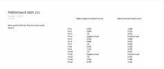
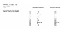
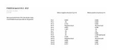
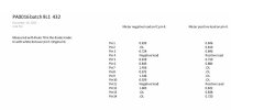
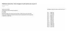
Bring this post back up to see if anyone has found the solution to these Pioneer PA0016 IC's. I bought two IC's on E-bay ( new batch numbers marked 1B24 211 Originals were 9L1 432), and before I place them in the14 pin socketed IC holders on the Pioneer VSX-9500S, I did measurements with my Fluke 70 in the diode test mode to compare to new ones with the old ones. I used pin 4 and pin 11 as my references. Pin 4 (neg) I measured pins 1,2,3, then 4,5,6 (pos) then measured pin 11 (neg) and pins 8, 9,10, then 12, 13, 14. Then I reversed the leads and measured the pins again. I did find differences, on one of the old IC had a short on pins 11 and 12 (when measured both ways). So with the new ics installed that help me find an open resistor R234 (10 ohm's). That's why on post 9 I had the high bias voltages on the outputs. So right now the VSX-9500s powers up with all the protection relays clicking in correctly. Rear speakers are working correctly, Center speaker is working correctly, BUT the mains are not working correctly. I can have a set of headphones plugged in headphone jack. ( main speaker relay off) and sound is okay at low volume, but as the volume is turned up ( seen on Scope) the positive collapses Yet all the positive voltages sources are correct . All the bias voltages for the outputs are too low. IE. pins 1 and 14 should according to the schematic should 1.1 volt and 2.4 volt I get 0.29 volts and 0.1 volt. All the other voltages on the PA0016( On both IC201 & IC202) are low? Fake PA0016 IC's ?
 

Attachments

  • SAM_4547.JPG
    SAM_4547.JPG
    88.3 KB · Views: 6
  • SAM_4548.JPG
    SAM_4548.JPG
    90 KB · Views: 5
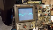
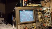
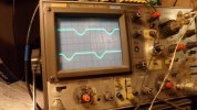
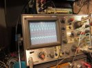
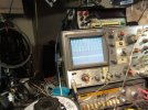
First picture almost working correctly, Second picture when the speaker relay is turned on ( have a speaker dummy load connected). Working on getting the sine wave photos uploaded soon.
 
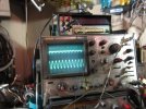
Using LINE in for 1khz input. Scope test point at output transistor emitter of Q2 & Q1. Relay for main speaker off with headphone being used. Low volume ( up to about 4 on the volume control scale) the sinewaves are okay. As the volume is turned up further the wave form distortion starts to appear with the start of the collapse of the positive or top of the 1Khz sine wave. And with more volume you both top and bottom wave form collapse as seen in pics.
 

Attachments

  • SAM_4551.JPG
    SAM_4551.JPG
    92.7 KB · Views: 4
  • SAM_4555.JPG
    SAM_4555.JPG
    87.7 KB · Views: 2
  • SAM_4554.JPG
    SAM_4554.JPG
    84.4 KB · Views: 2
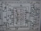
Schematic of the main amp of the VSX-9500S. Too bad Pioneer does not release the datasheet on the PA0016 IC.
 

Attachments

  • VSX-9500S b.jpeg
    VSX-9500S b.jpeg
    79 KB · Views: 19
  • VSX-9500S a.jpeg
    VSX-9500S a.jpeg
    100.3 KB · Views: 17
Last edited:
Voltages measurements on IC201 & IC 202 in the Pioneer VSX-9500S with the new (fake?) PA0016 IC's.
 

Attachments

  • IC201 IC 202 Measurements.jpeg
    IC201 IC 202 Measurements.jpeg
    24.8 KB · Views: 11
These measurements may help someone in finding out if the PA0016 IC's are genuine or not?
In Old IC 2 please note that is a blown IC Pins 11 & 12 are almost dead short.
Old IC 1, I will put it in one of the channels and see or measure if this IC could let the smoke out or work? Cause right now I do not have a working PA0016. I bought 4 of the new IC's batch 1B24 211, but all do the same thing and measure the same.
It would ready be nice if some could measure a known working IC. Hopefully you have it in a 14 pin socket or will remove it and then install it a new IC socket ( make sure you record the pin one orientation). Thanks in advance.
 

Attachments

  • New IC 1.jpeg
    New IC 1.jpeg
    24 KB · Views: 8
  • New IC 2.jpeg
    New IC 2.jpeg
    24.3 KB · Views: 7
  • Old IC 2.jpeg
    Old IC 2.jpeg
    23.5 KB · Views: 7
  • Old IC 1.jpeg
    Old IC 1.jpeg
    23.9 KB · Views: 9
Last edited:
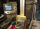
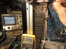
Okay some good progress. I installed one of the original PA0016 IC ( see Old IC 1 .jpeg ) batch 9L1 432 in one of the 14 pin sockets, and it worked!
My output transistors Q2, Q4 base voltages were as designed. All the voltages on IC 202 were also correct.:) When I added the Speaker A load it was not clipping on that side. So the SMOKE never came out.:):) I swapped the PA0016 (Old IC 1) to the other side( in the IC 201 position) and it also worked. All the bias voltages on Q1, Q3 were correct. Also okay when speaker A was switched on.
 

Attachments

  • Original Ic Pa0016 meaurements.jpeg
    Original Ic Pa0016 meaurements.jpeg
    35.8 KB · Views: 8
  • IMG_7484.JPG
    IMG_7484.JPG
    122.2 KB · Views: 9
  • IMG_7485.JPG
    IMG_7485.JPG
    123.7 KB · Views: 9
  • IMG_7487.JPG
    IMG_7487.JPG
    116.3 KB · Views: 10
  • IMG_7492.JPG
    IMG_7492.JPG
    130 KB · Views: 9
  • IMG_7489.JPG
    IMG_7489.JPG
    139.5 KB · Views: 7
  • IMG_7488.JPG
    IMG_7488.JPG
    128.9 KB · Views: 7
  • IMG_7494.JPG
    IMG_7494.JPG
    129.9 KB · Views: 7
  • IMG_7496.JPG
    IMG_7496.JPG
    111.2 KB · Views: 7
  • IMG_7500.JPG
    IMG_7500.JPG
    116.1 KB · Views: 7
I tried a jumper on the new PA0016 IC channel Pin 4 to Pin11, because I have seen some schematic with these pins connected together, just in case some IC's would need that connection to work correctly. Anyways it did not change the incorrect bias voltages.
The Question is what would you do if you knew that you have been sold Fake IC's on EBAY? I have not given this seller a review yet, because I want to make sure I was correct in stating that they were not Original IC's, and the IC's did not work because I not fixed the amp correctly.
 
Yes, I re checked the PA0016 is going to hard to track down. I would not buy any from China. I can not believe that Pioneer would not give a datasheet for this obsolete IC.
Has anyone working for Pioneer service department come across the datasheet for this IC?
Pioneer models that contain the PA0016 are: SA-970, SA-770, A-443, M90, M91, VSX-9300,VSX-7500S, VSX-9500S There possibly are many more models? Maybe we can make a complete list?
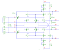
ItsGrarand there some forums that are attempting to reverse engineering this IC ( see attached schematic post-4991) or have some discrete components in place, but this IC seems to have no data sheet.
Has anyone have success with this circuit (post-4991)?
ItsGrarand did you ever try the circuit you posted in your post #5?
 

Attachments

  • post-4991-139829387346-thumb.png
    post-4991-139829387346-thumb.png
    61 KB · Views: 13
I have an M90a I'm working on that has this chip, essentially just a Japanese market version of the M91. Predrivers failed and sent full rail voltage to the chip and now I'm seeing about 78 volts to pins 8, 9, 13, and 14. Anyone know of a GOOD source for these chips? Or is eBay my best bet?
 
Back
Top Bottom