
• The move to the new server is done. There are some software and database maintenance updates in process. This has us passing the hat around to help out. We appreciate any donations. Seriously, even a dollar helps. The payment page may be found here - https://www.audiokarma.org/support.html

PA3004 Pin 4 question

merlynski

Curmudgeon Electronicist
The Pioneer SIP PA3004 protection IC is used in many of their products across all levels of build. My question is what voltage (or current) is needed on pin 4 to trigger the relay output pin 3 to go low and turn off the relay transistor. This questions assumes that all the other inputs are at appropriate levels to enable the relay to pull in and they stay that way. I understand (I think) logically how the PA3004 works but I cannot find an internal schematic (rather than the published logic diagram) for it. So please enlighten me with specifics if possible. Thanks much!
 
Last edited:
Register to hide this ad
look at the sx-980 manual .it explains how the protect circuit works .. they omitted to say voltage that will turn off the driver transistor though .. i would get offsets down first anyway as needs doing then look at the over-current side of things .
you could pull r5 and r6 first and then d2 to disconnect amp outputs to protect and over-current sense .
 
look at the sx-980 manual .it explains how the protect circuit works .. they omitted to say voltage that will turn off the driver transistor though .. i would get offsets down first anyway as needs doing then look at the over-current side of things .
you could pull r5 and r6 first and then d2 to disconnect amp outputs to protect and over-current sense .

Thanks for your reply, but I am not trouble shooting a particular system right now, though I have done so in the past.. I understand how the protection circuit works, for both offsets and overloads, and have studied the Wheatstone bridge circuit that activates the circuitry attached to pin 4. What I am looking for is the specific critical limits of the signal (voltage or current) at pin 4 that trigger its response. In other words I am looking for Pioneer chip design/engineering data. They may not have published it, so I am fishing in the AK pond for the data.
Thanks again :D.

EDIT: emphasis added
 
Last edited:
just had a thought and if its like a transistor it will take around 600mv to turn on .
:idea: Exactly the information I am looking to find out: is it an NPN transistor base that takes a minimum + voltage and + current to trigger, an FET (voltage, no current), a differential amp input (voltage, little or no current), an op amp/comparator, ? . . . I have been unable to find an internal schematic, that would provide a clue, at least. Anybody know if Pioneer published such a thing? Or if I had one to play with I could breadboard and reverse engineer it, that would be fun. Not willing to pull one from a working unit, and none of the carcasses I have have one still in it. If anybody has one they are willing to send me I would be glad to give it a try, I would even return it after I am done (PM me). I have enough schematics/service manuals of Pioneer gear from which to glean the external circuit parameters. The cheapest one I have found costs about $11 delivered from China, on our favorite auction site. I could do that too, but not till later in the year. :)
 
mad late night thought but it might be much like part of an earlier protection circuit crammed into it . AC part of it might narrow it down .. or that could be a feature ..i dunno just rambling .. :D
 
mad late night thought but it might be much like part of an earlier protection circuit crammed into it . AC part of it might narrow it down .. or that could be a feature ..i dunno just rambling .. :D
Like my sig says "When I don't understand . . ."
They say "Curiosity killed the cat", good thing I'm not a cat :rflmao:
If I had one I would test each of the inputs individually, while holding the others in the 'active' state so the relay was pulled in.
 
Usually about 1V to turn on. You can look at other protection ic's specs to see what they have, I have tested a Hitachi HA12002 part, iirc it was about +/-1.2VDC in either direction. Not totally symmetrical, but it does not have to be in perfect balance for this application.
The R network that is connected to the PA o/p will determine the sensitivity and max input current into the input node.
if you look at the sx-1980 PS sch they have Q301 turning on as the over current detector drive enable. Q 301 drives the 13VDC supply into the voltage divider made up of R306(1K3) & R307(11K) That is a hard turn on condition, so a maximum input V.
 
Usually about 1V to turn on. You can look at other protection ic's specs to see what they have, I have tested a Hitachi HA12002 part, iirc it was about +/-1.2VDC in either direction. Not totally symmetrical, but it does not have to be in perfect balance for this application.
The R network that is connected to the PA o/p will determine the sensitivity and max input current into the input node.
if you look at the sx-1980 PS sch they have Q301 turning on as the over current detector drive enable. Q 301 drives the 13VDC supply into the voltage divider made up of R306(1K3) & R307(11K) That is a hard turn on condition, so a maximum input V.
Thanks for the reply!

I was not aware of the Hitachi HA 12002. This is good info.

I have just about concluded that PA3004 pin 4 is fairly high impedance voltage driven input, as excess offset detection is through 75K ohm resistors. It does appear that pin 4 can also be triggered by negative offset voltage from the outputs, despite the possibility of reverse bias on the electrolytic cap connected to pin 4. I am assuming :rolleyes: that the low current and voltage duration would not be long enough to damage the cap before dropping (or not pulling in) the relay.
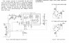
 
Tinkering with circuit values and ohm's law on a calculator tells me it will take an ~10 volt offset (on one channel) to produce a 1 volt dc level at pin 4. That's a pretty catastrophic failure, though it would only produce a ~12.5 watt momentary dc output to the (8 ohm) speaker before the relay dropped. Thoughts?
 
Last edited:
You are on track to figuring it out. Also look at another popular part NEC uPC1237, it has +0.62V & -0.17V switching threshold.
It is assumed that a bit of reverse bias on a ecap is okay, it a failure condition. The best is to use a BP or back to back ecap in that position.
 
i wondered whether the discrete circuit was crammed into the ic . :idea:
I don't think so, not identically anyway, there are a couple of components that wont fit, the 330 uF caps on the base of Q3, for example, and I don't see an external replacement. Some of the 950/1050 circuit is similar to the external components in the 1980 protection circuit. It looks to me like Pioneer came up with an IC (PA3004) that could be used almost anywhere with just a few external component changes, with the same basic circuit architecture. The SX-780 I just repaired uses the same IC and almost identical external circuitry.
 
Last edited:
Thanks for your reply, but I am not trouble shooting a particular system right now, though I have done so in the past.. I understand how the protection circuit works, for both offsets and overloads, and have studied the Wheatstone bridge circuit that activates the circuitry attached to pin 4. What I am looking for is the specific critical limits of the signal (voltage or current) at pin 4 that trigger its response. In other words I am looking for Pioneer chip design/engineering data. They may not have published it, so I am fishing in the AK pond for the data.
Thanks again :D.

EDIT: emphasis added
You've probably seen this from the service manual? It doesn't give component values, which is what you're probably referring to?

Capture.JPG
 
Back
Top Bottom