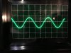
Here is signal at grid of first half of V1 (a 12AX7):
View attachment 964415
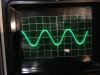
And after the first coupling cap after the plate of V1:
View attachment 964416
So far, so good, right?
Then there is a weird little tone circuit involving a few of the PIO caps and two pots leading to the second half of V1.
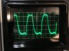
Here's the grid of the second half of V1:
View attachment 964418
It's starting to really clip and distort here - and the volume for these photos was only at 1 or 2!
Then after V1 it heads through a coupling cap toward the first half of V2 (a 12DW7) which is the start of the vibrato circuit.
Here's the grid of the first half of V2:
View attachment 964419
Yikes! Looks like some noise in there as well as distortion. Vibrato circuit does not really work, either.
After the 10 PIO caps in the vibrato circuit - by the time it gets to the power tube it's totally wack:
View attachment 964420
My plan is to remove each PIO cap starting at the input stage, test it for capacitance and leakage. If it is leaking, it gets replaced. Then I'll run the signal trace again and take a gander at the waves. I'll give the owner the bag of caps at the end and he can decide what to do with them. Owner says he is good with that - I'll let you know how it goes!