• The move to the new server is done. There are some software and database maintenance updates in process. This has us passing the hat around to help out. We appreciate any donations. Seriously, even a dollar helps. The payment page may be found here - https://www.audiokarma.org/support.html

parallel rectifier question

gadget73

junk junkie
Subscriber
I'm considering some possible tweaking to my Rauland-Borg amps to see if I can get a little more from them. Stock it uses 2 rectifiers, but at different voltage levels. One 5U4GB runs the plates, and one 5Y3GT runs the output tube screens. Regulation is not amazing with this setup. B+ on the plate supply drops by 13% from idle to full load, and the screens drop by 12%. I was thinking of using parallel rectifiers and installing EFB to supply the screens. The AC supply only drops by 3%, so my thinking is that with parallel rectifiers the regulation should improve. Haven't firmly settled on what rectifier.

My question is this.

The two rectifiers each have their own 5v winding. Am I better off paralleling these two windings to feed the rectifiers, or leaving them independent? Pin 8 will be connected together at the first cap, so its basically a question of fitting a jumper at pin 2 or not. I plan to wire things up so that both tubes are running full wave.

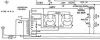
Schematic for the in-use power supply in this post

Rauland-Borg RA70, resistance is futile
 
Register to hide this ad
Am I better off paralleling these two windings to feed the rectifiers, or leaving them independent?

I would think that the 5U4 heater winding is a heavier AWG with a higher current rating than the 5Y3 heater winding.
Would paralleling each 5U4/5Y3 heater winding together be able to put out enough current for whatever pair of rectifier tubes chosen would draw?
Be it similar or dissimilar rectifier tubes?

My Altec amp uses two 5U4 with the 5 volt heater winding in parallel because there is only one winding. The plates are bridged for half wave.
 
I'm no tech by any means but my Fairchild 260 amplifiers use. 2 5v4/gz32 rectifiers so mabe look at the schematic for it and see what they did and why they did it .I'd be definitely interested in your thoughts and perhaps it might help you .
 
looks like a single winding. My Pilot SA-260 is also one winding for parallel 5U4GB's. I've never seen parallel rectifiers with two different heater windings, which is why I ask.

Current-wise, a single 5U4 will get the job done. I'm just trying to reduce the supply impedance to improve regulation. I'm not opposed to other rectifiers, but all of them are going to need the heaters hooked up somehow. I'm inclined to not parallel them but I figured I'd ask if there was some solid reason that I should.
 
Gadget -- you can't parallel the rectifier heater windings because in your case, the rectifier tubes have differing levels of AC voltage applied to their plates. That means their DC output differs as well -- and because the design uses filamentary cathode rectifier tubes, it means that the DC level present at each rectifier winding is different -- hence the two separate windings. Paralleling the windings then would try to equalize the DC outputs from two different AC inputs -- or am I not understanding correctly what you're trying to do?

Dave
 
I'm planning to run both sets of plates off the high voltage connection. The lower voltage tap will be disconnected. I'm just not completely sure what to do with the heaters.

With EFB installed, that lower rectifier won't be doing anything, so I was thinking of a way to re-purpose that second rectifier socket.

I'm prolly not understanding this. Both rectifiers will run off the same HV secondary lines? But, not the same 5VAC taps? :idea:
 
Correct. Originally this has 2 rectifiers, each at different voltage levels. Direct heat rectifiers put HVDC on their heater supply, so different output voltage means different heater windings. I want to make it a single output voltage supply using parallel rectifiers. I don't trust that either of the 5vac windings alone will run 2 rectifiers, so that means using both of them. Pin 8 on both rectifiers will tie together because it has to go to the filter cap. Pin 4 will go to pin 4. Pin 6 will go to pin 6.

The question is basically one of do I tie 2 to 2 or not. Electrically it should work either way, I just don't know if there is an advantage one way vs the other.
 
As they say, a picture is worth half as many words as I usually type per post. Now that its drawn I realize I could have done it differently for clarity, but I'm not re-doing it now.
 

Attachments

There is the issue of what two rectifier tubes do you plan to use? With dissimilar tubes used in the original design, the 5AS4 winding is likely a 3A winding, while the 5Y3 winding is a 2A winding. Since they will both run off of the highest voltage taps, you could consider using two identical tubes that will not overload the 2A winding -- like a 5V4GA or GZ34. Then tying the two pin 2 terminals together becomes a moot point. You would now have a nice B+ delay, but this will increase your B+ as well so watch out for any concerns with that. Since you are basically operating the two rectifiers in parallel from the standpoint of DC current draw, they will need to be the same tubes, and you will want to use balancing resistors at each plate terminal as well.

Dave
 
Just bouncing things in my noggin. You may want to parallel the 5VAC lines. Maybe, this will allow the 5Y3GT to "see" sag & rise in the 5U4GB's line. I'd imagine it would be nice for the screen voltage to change in parallel with the plate's voltage change, in real time?

Like I said. A random thought...
 
There is the issue of what two rectifier tubes do you plan to use?

It will be identical rectifiers, I just haven't settled on which one. I'd prefer 5U4's because I have them but 5V4 or 5AR4 are possibles. I also haven't ruled out using damper diodes if they will behave themselves on a 5v winding instead of 6v.

When you say balancing resistors at each plate, you mean low-ohm resistors between the rectifier plate and the transformer winding? How low can I go there safely?

I'd imagine it would be nice for the screen voltage to change in parallel with the plate's voltage change, in real time?

Thats kind of what it does now, but I'd like to reduce the sag. The screens will be supplied from an EFB screen regulator so they track as a fixed % of plate voltage.
 
Cool idea. I've thought about having two rectifiers for the ST-70. But I haven't seen it done. It would be easy to ditch the cap can and place the second rectifier in its place.
 
I also haven't ruled out using damper diodes if they will behave themselves on a 5v winding instead of 6v.

I've always pondered the thought of using two 6AU4 damper diodes for full wave in my Altec 345A. But like you mentioned, I've also wondered how would they react with 5 volts heating.
The 6AU4GT draws less current than all the rectifiers mentioned...1.8 amps versus 2-3 amps...not much, but nonetheless.
 
Back
Top Bottom