
• The move to the new server is done. There are some software and database maintenance updates in process. This has us passing the hat around to help out. We appreciate any donations. Seriously, even a dollar helps. The payment page may be found here - https://www.audiokarma.org/support.html

PAS-2 Weak Left Channel Help

Thanks for the readings.
Your filament is way too low. This explains the other readings.
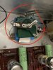
You need new filament rectifiers, that is the green thing in the middle surrounded by 2
electrolytic capacitors.
It can be done with 2 diodes 1n4005 , but you should also replace the 2 caps. An easier
solution is to replace with a kit from ebay :
https://www.ebay.com/itm/Tube-Heate...400608?hash=item5b59e80060:g:YcMAAOSwa55cLD6r
Cost $21

An even better module that also replaced the B+ can cap :
https://www.ebay.com/itm/Dynaco-PAS...355713?hash=item1c932e1781:g:XowAAOSwstJZRtGi
cost $42.5
 
I also want to add that I switched the tubes on each board and the readings followed the tubes for the most part. Does that matter?
 
I also want to add that I switched the tubes on each board and the readings followed the tubes for the most part. Does that matter?
Possibly, but it might not be significant. Start with getting the filament back.
There is a high risk for wrong actions if one changes several things. Fix one thing first.
 
Use leaded 60/40 or 63/37 for best and easiest result.
Thanks. Do you know if I can solder the wires in from the top or do I have to insert them and turn the board over to apply solder? Also, do you have diameter of solder you’d recommend?
 
Thanks. Do you know if I can solder the wires in from the top or do I have to insert them and turn the board over to apply solder? Also, do you have diameter of solder you’d recommend?
It's probably in the instructions, but my guess is that you can mount the board first and then connect
everything from the top, and solder there also. Which is convenient as the board does not move during
soldering. The third picture confirms this.
 
That’s what I thought it looked like in the pic too. Just wanted to make sure. Dude, thank you so much for your help so far. I really appreciate it.
 
That’s what I thought it looked like in the pic too. Just wanted to make sure. Dude, thank you so much for your help so far. I really appreciate it.
Welcome!
Let us know the result ( voltages and the effect of channel balance). You might not need new tubes !
 
So I removed the old heater (new one is coming tomorrow) and noticed the wires are a bit short coming from the transformer and the PC5 and PC6. Do you have a recommendation for replacement red and black wire from phono and line boards? All of the wire I see on amazon is stranded. Also, would it be ok to extend transformer wire with solder and shrink?
 
So I removed the old heater (new one is coming tomorrow) and noticed the wires are a bit short coming from the transformer and the PC5 and PC6. Do you have a recommendation for replacement red and black wire from phono and line boards? All of the wire I see on amazon is stranded. Also, would it be ok to extend transformer wire with solder and shrink?
Extending wires with shrinktubes over the solders is ok.
You might find it easier to route the filement connection on the overside of the chassies, make sure they are
as long from the boards and close to the steel as possible.
 
Extending wires with shrinktubes over the solders is ok.
You might find it easier to route the filement connection on the overside of the chassies, make sure they are
as long from the boards and close to the steel as possible.
You have me a little lost on this. Would you mind explaining that a little further?
 
Last edited:
You have me a little lost on this. Would you mind explaining that a little further?
I guess you mean the comment about routing wires from the supply board to the PC5 and PC6 boards.
The original wires is routed below the pc5 and pc6 boards. But routing them from above will be somewhat shorter
and also could be routed close to the chassies. Twist them whatever you do.
 
I got her in. I ended up just turning the board so the pc5/pc6 wires were closer to the pa211. The transformer wire attached to T2 was a bit of a stretch but it seems like it’s working out. I’ve only listened to one side of a record, but I will say the channel balance issue seems to have been resolved. I took new readings with 4 new JJ E83CC tubes, I might do another reading with OG tubes. Here are the numbers:

Front PC6
  1. 85.3
  2. -.007
  3. .686
  4. 0
  5. -11.57
  6. 110.3
  7. .031
  8. .718
  9. -5.705
Back PC6
  1. 94.5
  2. -.31
  3. .607
  4. .008
  5. 11.46
  6. 102.4
  7. .073
  8. .786
  9. 5.83
Left PC5
  1. 137.5
  2. 0
  3. 1.582
  4. -.180
  5. 11.5
  6. 164.1
  7. 0
  8. 1.17
  9. 5.767
Right PC5
  1. 139.5
  2. 0
  3. 1.544
  4. -1.91
  5. -11.06
  6. 163.2
  7. 0
  8. 1.139
  9. -5.748
Thank you!
 
Last edited:
The problem appears to be solved, but my experience with two PAT-4's and a PAS-3X, in every case, channel imbalance was caused by the volume control. At the time, which was several years ago, Radio Shack had pots with loudness taps which served. It took maybe five pots to get three which were balanced, but they were cheap.
 
My PAS2 had a bum control, but it was more of a bad tracking thing than an across the board channel imbalance. The left would be low at one point, at other points the right would be low. It moved back and forth. Its a common issue with old carbon volume pots. The two sections drift at different rates and things go funny.
 
Back
Top Bottom