• The move to the new server is done. There are some software and database maintenance updates in process. This has us passing the hat around to help out. We appreciate any donations. Seriously, even a dollar helps. The payment page may be found here - https://www.audiokarma.org/support.html

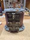
Pathetically dumb question here, how do I wire up this variac?

pete1729

Super Member
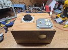
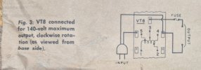
So I have wired this unit up according to the diagram below. I have the hot going to terminal 5 on the left and then coming off terminal 3 to the outlet. The neutral off the outlet goes to terminal 4, then to the neutral blade of the plug. The voltage DROPS when the knob is turned clockwise.

I would like the voltage to increase as the knob is turned clockwise so it matches the indicator scale.
20260904_164329.jpg
20260905_081554.jpg
 
Register to hide this ad
Still not sure why you want up to 140V out.

According to the connection plate on the side of your variac, for 140V output, you can use 4 and 5 as the input, with output coming from 4 and 3 as you have it connected now, or, you can use 1 and 2 as the input, taking the output off of 1 and 3. This should reverse the direction.

For 120V out, you use 1 and 4 as the input, and take the output from 1 and 3 for one direction, 4 and 3 for the other.

It looks from the diagram and construction that as you rotate the shaft clockwise, it moves wiper 3 closer to terminal 2/4 (decreasing voltage) and farther from terminal 5/1 (increasing voltage).

1788628847595.png
 
I most heartily and completely disagree. It is NOT a "pathetically dumb" question. That is the kind of label used when a person has the ability to ask a question and fails to do so. It is exponentially malignant dumb when the resources to provide information are so readily accessible and verifiable.

As for the ability to output a greater voltage, there are at least a couple of relevant points regarding that:

1. Why not have the ability to fully encompass a range of voltages if it is possible? Not everything that ever crosses a bench might need exactly 120VAC like a typical consumer electronics item.

2. If a person looks at it from a different perspective, someone with a 100VAC source might just want to be able to easily create an output closer to 117V.

Anyone want to expand that list? I can think of more. FWIW, I have a 600VAC output variac for things that are not table radios, Eye-Phone chargers, or curling irons.
 
If you haven't changed any of the wiring, is there a shaft on the other side of the Variac? The voltage plate and dial may have originally been placed there. In other words, the variac chassis is upside down.

:idea:
 
Yes, shaft on both ends. Or they're thinking of screwing that scale to the back of the knob instead of the panel. Move the hot to 2 (tap), neutrals to 1 for 0-140 to match the scale. Or hot to 4 if you want 0-120 (0-120 on opposite side of scale?). These days there's less need for step-up with line voltage typically above 120.

I use 140V setting all the time for testing transformers - if it'll take 140V without the input current climbing drastically, I know the transformer is good for 50 Hz, and that the core flux at 60 Hz won't be leaking too badly (60 Hz-only transformer will saturate on peaks, with a lot more hum coupling)
 
As for the ability to output a greater voltage, there are at least a couple of relevant points regarding that:
Yes, in a completely unconstrained context it is easy to conjure general reasons to output higher than line voltage.

However, in =this= context, in the 60Hz USA, where this device is being used as a safety limiter for suspect or vintage equipment, the intent is to provided a controlled, safe, less than line voltage for purposes of testing. When using a device like this, on a suspect device under test, the intent of the user should rightly be focused entirely upon the equipment itself, intently watching and listening for any signs of trouble, and not on the voltage scale or position of the variac knob as it is being increased. By setting the hard stop maximum of the variac to full unattenuated line voltage, you arrive at the intended destination successfully- full wall voltage, ready to be then plugged into the wall. When testing vintage equipment that was most often originally designed for LESS than modern wall voltage, this full wall voltage is stressful enough. Now, running this vintage equipment at wall voltage +17% can possibly be destructive. By configuring the variac to run all the way to 140 with no stop at 100% of actual line voltage other than a meter reading, the only thing preventing possible damage is the mindful attention to watch for and stop the dial at 100%. The real risk of accidentally running over this point and damaging equipment is not worth the novelty or rare instance where greater than line voltage might be needed.
 
Yes, shaft on both ends. Or they're thinking of screwing that scale to the back of the knob instead of the panel. Move the hot to 2 (tap), neutrals to 1 for 0-140 to match the scale. Or hot to 4 if you want 0-120 (0-120 on opposite side of scale?). These days there's less need for step-up with line voltage typically above 120.
If it does have a shaft at both ends, I'd just take the variac chassis out of the wooden cabinet and flip it over. No rewiring would be needed.

:idea:
 
You can easily install a switch to toggle between the 0-120V and the 0-140V range when needed. I would strongly recommend this; we all have oopsies sometimes.

I'm inclined toward that idea, but there is a fixed scale on top.

I'd also like to add small panel mount digital volt meter and digital ammeter. Anybody want to spec those units out for me?
 
For the record, that’s not a “dumb” question, it’s what we’re all here for, to provide knowledge based on our experiences.

When I got my first variac, I didn’t know why it went from full voltage to zero; I just didn’t understand the hookup!
 
For the record, that’s not a “dumb” question, it’s what we’re all here for, to provide knowledge based on our experiences.

When I got my first variac, I didn’t know why it went from full voltage to zero; I just didn’t understand the hookup!
:thumbsup:

Those Topaz Ultra-isolators can be a challenge, too!
 
If you haven't changed any of the wiring, is there a shaft on the other side of the Variac? The voltage plate and dial may have originally been placed there. In other words, the variac chassis is upside down.

:idea:
I had or still have one with the shaft that can slide one way or the other. Flip it 1 way for voltage increase as you go CW with it , or flip it, move shaft to other side for voltage decrease as you go CW. Slap faceplate on which end is applicable. It's an old oddity for sure. May be milsurp.
 
I'm inclined toward that idea, but there is a fixed scale on top.

I'd also like to add small panel mount digital volt meter and digital ammeter. Anybody want to spec those units out for me?
Each meter should be capable of reading in excess of your maximum parameters of your unit for better accuracy. Internet search should provide lots of options.
 
Back
Top Bottom