• The move to the new server is done. There are some software and database maintenance updates in process. This has us passing the hat around to help out. We appreciate any donations. Seriously, even a dollar helps. The payment page may be found here - https://www.audiokarma.org/support.html

PCB's, what's the worst makes for track lift?

John3655

Well-Known Member
In my experience, some Philips and NAD lift their tracks with the slightest application of a soldering iron, made even more difficult by the way their insertion machines staple the devices to the board so everything is difficult to remove.

What's the best and worst you've experienced?
 
Last edited:
Register to hide this ad
1950s-60s vacuum tube equipment is also really terrible for it. Heat and age kills the adhesive holding the copper to the board and it basically just falls off when disturbed.

The same style boards were used in my 1964 Sony solid state tape deck, and while it wasn't quite as terrible as tube gear it wasn't good either. Luckily none of the traces that make up the card edge contacts peeled loose.
 
I was surprised when traces in the Tandberg 2075 I was working on lifted so much. I use a Hakko desoldering gun, at setting 2, am aware of lifting problems and therefore spend as little time as possible to heat the joint... but still had more than normal number of lifted traces.

Staring at the results and listening to fellow AK'ers, the more-narrow-than-other-manufacturers traces lifting made sense. There's less width to the traces, a lot less, and therefore less adhesive underneath.

The Tandberg is still one the better, more interesting designs... and it is definitely one of the better receivers I've worked on, but those narrow traces really change how one should approach diagnosis and repair.
 
I worked on a 2080 and a 2060. Definitely had some trouble with the 2060. It had something spill in it and I ended up replacing every single part in the power amp on one side. A fair number of the traces lifted but I thought maybe that was related to the spill.

The 2080 I think was just a popped set of output transistors and an emitter resistor, nothing too major. Don't recall serious issues with that one but I didn't actually have to do very much on the PCB itself. Definitely interesting construction. Packed in there pretty good but designed in a way that it wasn't actually very difficult o work on. The sections could easily be pulled apart to access the stuff below. I believe the 2080 and 2075 are very nearly identical in construction and overall design.

and yes it did sound quite good. Better than the 2060 IMO.

I did a mid 60s JBL solid state amp, that one caused me some grief. SA-260 I want to say, something 260 anyway. Another of those early non-coated circuit boards that doesn't hold together real well. Smoked output channel, and once that was fixed the preamp section showed a ton of problems related to bad caps, so that all got rebuilt. Miserable construction on that one. It basically cracks in half at the middle to get things apart, but you can't fully split the chassis without unsoldering a bunch of wiring that is hard to access. Sounded good once it was working but not a lot of fun to do.
 
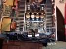
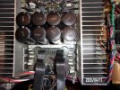
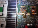
When I replaced the main filter caps in my old Onkyo M-508 amp it had several bad/lifted traces that where a PIA to repair. This is its third set of main caps and if they go bad the board is likely to be irreparable...
6. bad traces .jpg
 
Why is it eating so many caps?
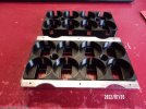
I've had it since 1986, and used it nearly daily until 2020. The caps get hot because they are sandwiched between the heat sinks sitting on a metal tray that is screwed to the heat sinks. While this one is a "dual voltage" model it was designed to run 72V on the main rails on 100 volt Japanese current, but when run on U.S. 115-120 volt current the rails measure close to 85 volts while the caps were only 90V. This last time when I recapped the whole thing (July 2022) I put in Cornell Dubilier 100V caps and have them sitting on a 3D printed plastic block. My laser temp gun shows them running 45F cooler than before (120F vs 165F)- they should last longer than I do....
2. new cap block 2.jpg109_2775.JPG
 
Must be some amp to run rails that high and have so much capacitance.
For 80's tech it is a pretty good sounding amp, but the capacitance is not that great, only 80,000uF. My newer Parasound A21+ and Schiit Tyr mono blocks have better sound quality and much more reserve power, they are just not as pretty! (A21+ has 108,000uF, each Tyr has at least 160,000uF and a 12lb choke). My Infinity RS4b speakers (1.6ohm dip at 35hz and a 1.7ohm dip at 1.8kHz ) would send the M-508 into protection if played too loudly, but the A21+ laughs at them.
 
Last edited:
I rarely have trace lifting issues with Tandberg equipment, but I use a Metcal iron and am pretty fast on the removal so it doesn't get a chance to cook the board enough to cause that damage. Always tin the tip first, use light gauge solder, flux if you need it and don't go low on tip temp, it's the speed (or lack thereof) not the tip temp that causes most of this type of damage.

John
 
I've had it since 1986, and used it nearly daily until 2020. The caps get hot because they are sandwiched between the heat sinks sitting on a metal tray that is screwed to the heat sinks. While this one is a "dual voltage" model it was designed to run 72V on the main rails on 100 volt Japanese current, but when run on U.S. 115-120 volt current the rails measure close to 85 volts while the caps were only 90V. This last time when I recapped the whole thing (July 2022) I put in Cornell Dubilier 100V caps and have them sitting on a 3D printed plastic block. My laser temp gun shows them running 45F cooler than before (120F vs 165F)- they should last longer than I do....
View attachment 3478256View attachment 3478258
So Yesterday I worked on a fellow members M-508 putting in new relays and touching up a few solder joints that were looking questionable. This amp came from a Military BX in Germany and is switchable 110V or 220V, unlike mine that came from Guam and is switchable 100-110-220-240V. The power rails were running right at 75V (spec is 74.8V) and its original main filter caps from 1987 showed no signs of any issues whatsoever (10,000uF 90V Nichicons). The heat sinks were measuring 112F to 117F, main caps 95F with the top off, 115F to 120F with the cover back on. I wonder how much cooler they would run if they were on the plastic block instead of right on the tray. I ran it a bit before opening it up and there was some scratchiness at low volume that was not from the preamp. I found one of the notorious transistors at the back of the board had a slightly loose connection (it is very common to have both of these transistors have cold solder joints) and the legs were bent in an "S". After fixing that issue and putting in the new relays the sound from this amp had deep controlled bass and sweet highs, just a damn great sounding amp !

Apparently this amp has always been running very high sensitivity Klipsch speakers with reasonable ohm loads. Mine never had it so good, as I used it to power my Infinity RS4b speakers for 35 years. The RS4b are supposed to be nominally 6-8 ohms but have been measured to dip to 1.7 ohms just below 2Khz and 1.6 ohms at the bottom of their range at 35hz... they sure put my old M-508 through some torture over the years ! If I had used it with some non-power hog speakers I might have only had to change the main filter caps once, not three times. I now use it to run a set of 8 ohm Monitor Audio Silver 100 7th Gen that only dip down to 4.9 ohms at 170hz- it should outlast me by many years !
109_4079.JPG109_4074.JPG
 
Last edited:
I've made a fair chunk of money fixing broken/lifted traces on PC boards over the years. Most of the damage was due to too much heat for too long when someone with bad soldering skills tried to "fix" something. But other times it's just abuse.

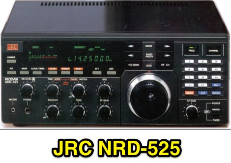
One of the extreme cases was on a JRC NRD-525 Shortwave receiver. I bought the radio used in 1987 at Universal radio. It was only about a year old.
jrc-nrd-525.jpg

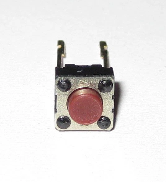
As time went by, it was sold to a friend, who sold it to another friend. One day, he calls me and tells me that the keypad keys have pretty much all failed. He's all upset, thinking that the 10 year old radio was "worn out". I thought, "Huh? How is that happening?". The keypad are literally metal shells put over the switches shown below, and basically are bulletproof. Like these switches:
s-l1600.webp

So I take the radio, and the PC board behind the keypad was just trashed. Cracked PC board in a couple of places, about a dozen traces broken or coming off the board, and it's just a mess. The board wasn't very thick, and the traces were pretty narrow and the flexing just wrecked it.

Since I knew the two owners previous to him had no issues with it, I knew he had to be the one who damaged it. I decided to replace all the keypad switches, they were really cheap, even for the "genuine" JRC ones. I ordered them, and while I waited for the switches to arrive, I wanted to see how he was pushing the keypad buttons when he used them. I met him somewhere and he was pressing them almost like he was angry, and I said, "Why the hell are you pushing them that hard?", and then very lightly tapped on them to show him the pressure he should have been using. Once he saw how insanely hard he was pressing on those buttons, he understood he was the cause of all the damage. Between some epoxy, one of those trace rebuild pens, wire and crazy glue, I fixed all the damage, and I guess I did a good job, as it's lasted well over 20 years. My only regret was the price I gave him to do all the work. Oh well.
 
Well I'm glad they paid you something for the work, almost sounded like they expected some sort of infinite guarantee from you.
I was the second of 5 owners, so he wasn't expecting anything from me, except possibly fixing it for less, and it turned out it was a lot less, than say Universal Radio. Ideally, the whole front panel PC board should have been replaced, but at that point, they were already getting kind of scarce, so I went with fixing it. It was just mechanical, so I wasn't worried about causing any really bad issues if it went wrong. That it turned out to have lasted so long is kind of impressive. I should have charged him at least double what I did for the work, which took a fair amount of time, as I had to take the whole front panel apart, repair the trashed PC board, then repair the traces and replace the switches, which were probably fine, but since he had pressed them so insanely hard, I just wanted it to be done in one shot and not have to go and take it apart again. He was pressing them so hard, the plastic front panel was showing the whitish stress signs between the keys. About the only cosmetic thing that ages badly on the 525 is the paint used on the black plastic wears off and the shiny black shows through. The problem with the one I have now is the display is so dim when it's first turned on, it's almost impossible to tell what freq it's on. An hour or so, and it's OK in a dark room, and it takes about 9 hours to be usable in a daylighted room. All those great old SW receivers are starting to have signs of old age creeping in. Filters failing, clock chips, flourescent displays fading, and in one case, the NRD-515, a real killer of an issue, the tuning dial encoder is an oddball magnetic encoder, and it failing is pretty much a death sentence. Someone was working on an optical encoder swap, but I don't know if it ever really worked or not.

 
I was the second of 5 owners, so he wasn't expecting anything from me, except possibly fixing it for less, and it turned out it was a lot less, than say Universal Radio. Ideally, the whole front panel PC board should have been replaced, but at that point, they were already getting kind of scarce, so I went with fixing it. It was just mechanical, so I wasn't worried about causing any really bad issues if it went wrong. That it turned out to have lasted so long is kind of impressive. I should have charged him at least double what I did for the work, which took a fair amount of time, as I had to take the whole front panel apart, repair the trashed PC board, then repair the traces and replace the switches, which were probably fine, but since he had pressed them so insanely hard, I just wanted it to be done in one shot and not have to go and take it apart again. He was pressing them so hard, the plastic front panel was showing the whitish stress signs between the keys. About the only cosmetic thing that ages badly on the 525 is the paint used on the black plastic wears off and the shiny black shows through. The problem with the one I have now is the display is so dim when it's first turned on, it's almost impossible to tell what freq it's on. An hour or so, and it's OK in a dark room, and it takes about 9 hours to be usable in a daylighted room. All those great old SW receivers are starting to have signs of old age creeping in. Filters failing, clock chips, flourescent displays fading, and in one case, the NRD-515, a real killer of an issue, the tuning dial encoder is an oddball magnetic encoder, and it failing is pretty much a death sentence. Someone was working on an optical encoder swap, but I don't know if it ever really worked or not.
There are some videos on YouTube about how to fix fading vfds. Basically involves applying a higher than normal voltage (9v pp3 battery) briefly to burn off the accumulation of impurities causing it to be dim, theory being the normal 5v isn't enough to burn them off. The risk is overdoing it and burning the filament out but might be worth a try. I tried it with a Philips cd753 which suffers premature dimming as the display is still on but blank when in standby hence basically on 24/7 for years. Improved it a little bit but I didn't apply the voltage for long.
 
Yeah, I saw a couple of fixes for them, but if I mess it up, the thing is useless unless it's hooked up to a PC. It uses an oddball cable that I sold off when I got more computer compatible radios over the years and so I would have to buy one on Ebay for $$$, or modify the back of the radio to use a standard serial cable. Or find a front panel with a good display on it, kind of like a pot o' gold at this point. That's the problem when stuff uses custom display modules. When they stop making it, they become very rare and expensive. I have some old dead police scanners in a drawer that I keep just in case the display on the ones I have that work die. They aren't really fancy, just basic black LCD on a silver background, but I have had one die suddenly about 4 years or so ago, and those corpses saved me from either buying a corpse off Ebay and gambling the display worked, or just retiring a fully functional but "blind" radio. I took the dead display out of it and carried it around listening to it, and it made a lot of people laugh. It just had a hole where the display went, and after a couple of days, I took one out of a corpse and instant fix. I had a radio gifted to me with a failing LCD display and I easily found a replacement, new, but it cost more than a used radio did! I just put it in my dead radio drawer and used the front panel off it to fix one a friend's dad broke somehow. The panel is kind of flimsy, and somehow he had broken the lower right corner. Ebay wanted like about $80+ for one, I put it in for him for a meal at Arby's. I did it cheap because I wanted to help him out, and I would guess his son would give me that radio when he died. And he did. I still have it, and it works fine.

The future is going to be bad for a lot of cars when they get old, and the display panels fail. They are expensive new, and I'm sure that they won't make all that many for much longer and you can't just wire up a toggle switch to turn something on or off anymore.
 
Back
Top Bottom