• The move to the new server is done. There are some software and database maintenance updates in process. This has us passing the hat around to help out. We appreciate any donations. Seriously, even a dollar helps. The payment page may be found here - https://www.audiokarma.org/support.html

Phase Linear PL-400 Series One Bridge Rectfier Question

Hello drp10003, Please do not take this the wrong way or thinking it comes from me. Over on the POLK site most over there hate anything Phase Linear related going as far as calling them Flame Linears. Now I have heard that they did have some sort of tendency to either light up the amp or the speakers they are pushing. I never saw this happen and a few friends had PL400 plus the 4000 pre amp w/ the joystick. I did see that you were installing a DC RAIL protection so there must be a bit of truth to this or an abundance of caution. I run an Adcom GFA- 555 w/o this protection and I've had it for over 11/12 years and the thing is from the 80's. I want an honest comparison from you if you could on both amps and would you take the Adcom ($300) over the PL. Audio Classics rated the amp @205 a side when bench testing it on I guess a trade in. I would like from you an honest comparison between both amps and if all the mods were not being installed in your PL would you take it over the Adcom stock out of the box if you will. I think my next pre amp will be either a PL4000 or the newer Carver 4000II no joy stick which to me is a bit of a gimmick because once you set the thing how many times are you actually going to use it. I hope your still around or of course anyone can please chime in. I have only seen a few PL 400s and even less PL4000s going for quite a few hundys......Lew


Hello, I have two PL-400s. The first one, the one you see here that I am working on right now, is a Series One amp, and the other is a Series Two with the cool LED meters and L/R gain controls. Now, to be honest, I've only listened to the Series Two amp for only about a day demoing vinyl in my living room before a finally put it in storage in my garage. The reason why I did this is because it is totally stock with no mods - not even a speaker protection circuit. And I was afraid I was going to melt my speakers like they say (Flame Linear). It is my opinion and that of the previous owner of Series Two amp that a speaker protection kit was needed before any speakers be hooked up to it. I think the previous owner was using an inline fuse somewhere on the speaker wire or his speakers had fuse protection built inside the cabinets, probably part of the crossover network. My speakers I built myself from a DIY kit and they do not have any speaker protection circuits or fuses built into them. I know because I built them myself.

I am not gonna use either amp until I have installed the Watts Abundant Speaker Protection Kits. The series two amp that I put up will also get a capacitor upgrade. And in due time, it too will get the full WOPL treatment.

As for the sound.......

I tried very hard to forget the sound of the stock PL-400 Series Two amplifier. Like I said, I only listened to it for about a day demoing vinyl before I put it in storage. This may sound crazy, but I want to do a side by side comparison of the MODDED WOPL SERIES ONE amp that I am working on right now and the stock SERIES TWO.

Here is what someone from HERE, AUDIOKARMA posted about the WOPL (MODDED White Oak Phase Linear) Phase Linear Amp, comparing Solid State to Tube:

"A WOPL would change a lot of peoples opinions of SS amps. They sound sweet and warm, have seemingly endless headroom and gobs of pure power. I left tubes a LONG time ago for SS. This was after having McIntosh 275's and a Fisher SA1000. They just did not deliver what I was looking for but did sound fine otherwise for low level listening. A Mark Levinson 333 changed me from McIntosh and the WOPL forever trailers the Levinson [I might have this etched on my tombstone]. Any tube amp I have had has not had that punch you in the face impact though the McIntosh 275 came damn close, just was very finicky depending on temperature and never could give the wicked low frequencies without impacting the mids."

I was very fortunate to find and purchase not one but TWO Phase Linear PL-400s locally on craigslist for very very reasonables prices. The Series One I got was a steal at 100 bucks. It looks like hell but the guts and wires and transformer are in perfect condition, or in other words, the perfect PL-400 to modify. And that is exactly what I am doing with it.

If you can snag one on the cheap, then go for it. If you can snag one on the not-so-cheap, then heck go for it. They are probably not the most reliable amps ever built, they don't have any speaker protection at all to speak of, but damn if they ain't fun to own!

Sorry I can't help you decide now, but after I am finished with this amp and it is up and running with hours of listening behind me, I could tell you more. That could be months from now.....
 
Last edited:
  • Like
Reactions: mbz
Hello everyone.

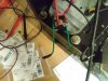
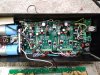
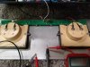
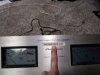
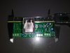
OK, some big things are happening. I got my WATTS ABUNDANT boards in the mail, and the parts to populate the boards from Mouser, too. Also, I went ahead and ordered two new bridge rectifiers (35amp/400volt from Mouser) and eight new capacitors (4 each 0.01uf/400volt from Mouser) for the power supply and upgraded power capacitors. I soldered the caps to the top of the BR like they say in parallel with the diodes (photo below). And also very helpful for discharging the huge power supply capacitors, I ordered two big flame resistant resistors (from Mouser), one for each capacitor. It takes several minutes to discharge both capacitors and the resistors heat up a bit and get warm to the touch, but that ridiculous amount of flesh-burning power gets dissipated without any flash&bang drama - a must!

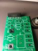
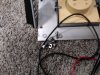
You can see from the photos below how the boards are screwed to the binding posts - brilliant!

The RCA posts are new, too - fantastic quality parts there.

Also, you can see two resistors and two capacitors are missing from the board. Those are the R/C zobel networks. The WHITE OAK boards have them so it would be redundant to have them too on the Watts Abundant board. This is the correct method according to White Oak. Don't worry, these parts are in parallel to the circuit (not series) so doing nothing but leaving them blank (no jumper wire needed) will not stop the circuit from working. The relay is massive. I soldered everything up in about two hours - I took my time and built two boards at the same time. The electrolytic capacitors and the diodes all need to be soldered in in the correct orientation, along with that IC chip on the right. The Phoenix connectors and the relay holder are pretty self-explanatory as to their orientation. Easy if you take your time. The rest of the parts (resistors and caps) can go in in either direction.
 

Attachments

  • 1128180752.jpg
    1128180752.jpg
    58.4 KB · Views: 176
  • 1128180751.jpg
    1128180751.jpg
    62.2 KB · Views: 174
  • 1128180749.jpg
    1128180749.jpg
    76.3 KB · Views: 174
  • 1126181240a.jpg
    1126181240a.jpg
    48.7 KB · Views: 175
Last edited:
Hi all,

TESTING TIME

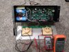
So, after I installed the new bridge rectifier w/ capacitor modification, installed the new pair of capacitors, and installed the new Watts Abundant speaker protection kit (with no wiring), I went ahead and retested everything.
I plugged in the amp and measured VAC at each individual red wire on bridge rectifier and black ground wire - measured the same at 63VAC each. Across the red wires measured 126VAC (63VAC+63VAC).
VAC at the grey and yellow wires that power the VU meter lights measured the same at around 10VAC give or take.
Both +/- VDC measured the same at +/-87VDC. To get these measurements, I clipped the black alligator clip of my multimeter to the grounding bar and measured voltages at both capacitor outputs (+87VDC & -87VDC respectively)

Now for the fun part, the speaker protection kit: I unplugged the amp and discharged the capacitors using the flame-resistant resistors. Then I wired up the blue wire from the diode bridge to the AC input of the protection board. Next I ran a ground wire from the grounding bar to the ground input of the protection board. And finally, I ran a test wire from the +80VDC fuse holder to the +DC input of the protection board. I plugged in the amp and BOOM! AN EXPLOSION!......no... that did not happen. The relay just clicked on after a few seconds delay as it should. When I unplugged the amp, the relay immediately clicked back to its original position. I did this several times (click.....click.....click.....click). My pride swelled to unimaginable heights. Everything seems to be in working order.

See you soon with WHITE OAK boards at the ready!
 
Last edited:
HELLO AUDIOKARMA!

I'm BaAAAaaaack!

It's been a while since I posted anything about the WOPL restomod of my PHASE LINEAR PL 400 amplifier. But that doesn't mean I gave up! Oh no, on the contrary. In fact, I've been busy doing other audio-related things, mainly building a set of large 3-way speakers that I plan to use in conjunction with a PL 400 amplifier. Also, I've been busy remodeling my shop. I added a man cave in the corner where I now have all of my audio equipment set up on custom-built shelves. A really nice leather chair and carpeting on the floor round everything out. I used that old MAXELL 'Guy Getting Blown Away in a Chair' advertisement as inspiration for my man cave setup. Since this thread is about SOLID STATE audio devices, I'm not gonna muddy the waters by attaching photos of the can cave - I will start a new thread in the appropriate section for that, later on.

Anyway, I recently ordered the kits from WHITE OAK AUDIO and they should arrive within the week:

PL 400 Control Board Kit
PL 400 Backplane Board Kit
PL 400 LED Light Kit for the VU meters
Output Transistors (16 total)
Wiring Kit (New wiring that connects the control board to the backplane boards)

It's Spring; it's getting warm outside; it's time to get back to work on my WOPL PL 400 Amp!

See you'all soon!
 
Wouldn't be better to just let the guy that bought the drivers answer the question? :dunno: I'm not being an ass, I am familiar with what WOA sells. What is in your PL400?
The PL-700b that I rebuilt for friend a couple of years back has MJ21195/96's in it that I sourced from WO along with their chassis kit. My thinking was that if he hadn't yet received the kit then he may not yet know the complete contents of it.

Sorry I didn't mean to piss in your thread, you may continue not being an ass...
 
Hey-hey,

I got all of my kits from WHITE OAK AUDIO, except the LED light kit; which is in transit and should be here sometime this week.

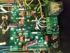
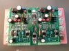
I've already soldered up the CONTROL BOARD KIT (PHOTO BELOW). It went surprisingly well. White Oak does a great job of separating the components into identifiable plastic baggies. All you have to do then is open up a plastic baggie (with a descriptive info sticker stuck to the outside) and solder in the components (R1, R2, etc etc.). Rinse and Repeat. I suggest doing the diodes and the resistors first. It's much easier to solder in those little buggers first when there are no other larger components in the way. After that it probably doesn't matter what components you solder into place.

There are two setups available: Quasi-comp and Full-comp. Of course, if you are doing the full WOPL treatment with new a backplane kit, as I am doing, then you Must go with the full-comp setup. The control board is laid out best for this configuration anyway.

The photo below of the Control Board shows a finished product. BUT BUT BUT, I have to REMOVE two capacitors (the two square blue ones at the bottom of the board, left and right channels). They are meant to be used with the quasi-comp setup. I left them on there to show everyone how it's somewhat fairly easy to goof up and install parts from one setup on another setup (full-comp on quasi-comp or vice versa). You have to pay attention to what's written on those baggies. There's not much of a difference between the two setups - a handful of components at the most - but it can happen if you are not careful.

The packaging from White Oak is perfect. Everything is labeled. I just didn't read the information on that particular plastic baggie holding those two capacitors ('for quasi-comp use only'). But I accidentally soldered them on anyway - my mistake. So now I have to remove them. SAD.

Please do not go by my photos. Reference only, please. Go by the White Oak Audio Documentation instead.

The documentation is perfect as well. If someone screws something up, it's probably going to be the person soldering the board together. Or in other words: TAKE YOUR TIME AND FOLLOW THE DIRECTIONS!!!

Having two different configurations adds a bit of confusion and anxiety, to be sure. So study the schematics and read everything first.

Also. There are a few places on the board (left and right channels) where nothing gets installed at all. They get left totally blank in either configuration. This too can add a bit of confusion, thinking one might have forgotten or lost some parts, or maybe White Oak did not send everything.

READ THE INSTRUCTIONS.

The transistors are ON SEMICONDUCTOR: 8 of MJ21196G 8 of MJ21195G
 

Attachments

  • 0402191024.jpg
    0402191024.jpg
    109.4 KB · Views: 147
  • 0402191015.jpg
    0402191015.jpg
    69.8 KB · Views: 151
Last edited:
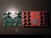
OK, I got the LED light board kit in the mail, but today I'm gonna talk about the backplane boards. There are two of them. And the reason why there are two doesn't necessarily have to do with there being two stereo channels (one separate board for each channel), but more because there is a thermal switch that gets in the way of having one LARGE complete backplane board, and it's located right smack-dab in the middle of the chassis (PHOTOS BELOW). There are jumper wires that go from one backplane board to the other (left to right) and BOTH positive and negative voltages are present on each board. Which means that half(?) the electronic components on the left side board are getting +80 volts and the other half(?) are getting -80 volts. So too with the right side board. Confused yet???

The speaker protection kit from Watts Abundant is still there on the right side of the chassis. It barely clears the right side backplane board. A tight fit to be sure. But I'm glad it's there. It makes making the final wiring connections a million times easier. Just screw the wires into those three phoenix connectors!

On the left side you can see my custom built grounding bar. Another life saver. Just look at all of those white ground wires sticking out of it! And not one drop of solder was used to make those connections. All screws and eyelets.

The only wires that cannot be removed without de-soldering are the four wires that come off the fuses and go to the left backplane board. Those are the ones that power the whole amp +/-80 volts. I thought about building a phoenix connector-like wiring strip and securing it to the left side of the chassis where these four wire would then connect together using screws. Four wires would come off the two fuse holders, go to the strip, and then four more wires would come off the strip and go to the left backplane board. Then ALL the wiring becomes plug and play more or less. Maybe in the future.

White Oak says that soldering up the backplane boards takes ADVANCED skills. But I found them to be somewhat easier to assemble than the control board. There's really not much to them. The hardware that connects the output transistors to the backplane boards (PEM NUTS and these little output transistor leg/plug thingies) were rather quite easy to solder on the boards. I did not have any problems with any of that stuff; you just have to take your time. White Oak makes it sound like it is much harder than it actually is. Again, just take your time, and everything will go quite smoothly.

The hardest part (but not really) is getting the output transistor legs installed through the backplane boards from the back side of the chassis/heatsink. You have to align the transistor legs just right in order to get them to go through these really small openings. And the great thing about them is that you do not have to solder in the legs to the backplane board afterward! I don't know what these things are, but they have little spring-loaded tabs inside of them. They are the tiniest little plugs I've ever seen, and the transistor legs have to fit just right. But once you get them in, then the spring-loaded tabs (tiny, tiny tiny little tabs inside these tiny tiny little plugs) make the electronic connection. If you blow an output transistor, then you just simply remove it from the back and replace it with a new one - no de-soldering required.

I would upload the assembly notes for the backplane boards, but the file size is too big. Then you could easily see what I am talking about. Alas....


It's the wiring stoopid. There're wires going everywhere. If you can get the wiring under control from the beginning like I did, then this whole process is a thousand times easier.

Next up: TESTING AND FINAL ASSEMBLY. See you soon!
 

Attachments

  • 0413190719a.jpg
    0413190719a.jpg
    112.6 KB · Views: 159
  • 0413190720.jpg
    0413190720.jpg
    118.5 KB · Views: 160
Last edited:
The ground bar is a good addition and way better than the stock flimsy ground strap. I machined a piece of .375" copper plate to fashion a central ground bar in the 700 I refurbed.
The wiring is a pain in these old P2P wired amps. The cramped interiors of the old PL chassis doesn't help either. Luckily you're eliminating some of the original rats nest with the WO boards.

Your work looks great so far I'm sure you're ready to get it fired up and tested.
 
SUCCESS!!! Mfckers! I have officially attained God-like status! (Although my wife begs to differ.)

Greatest. Amp. Ever. Why are you'all still defiling your ears with whatever cheap, dime store garbage you have that you call an amplifier???

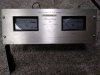
As it plainly states right there on the faceplate: WATTAGE FROM GOD (PHOTOS BELOW)

Anyway...after a bit of fussing around with the wiring, again, and finally testing row after row of output power transistors until ALL SIXTEEN of them were installed and functioning properly, I went ahead and hooked this beast up last night. Yikes! Holly Cow! Loud and clean. Deep controlled endless bass. I cannot get over the bass output. I built a pair of three-way speakers just for this amplifier: Each speaker having a 12" 8ohm subwoofer, 4" 8ohm midrange, and a fine sounding 1" 8ohm dome tweeter. I drew inspiration from the old classic JBL L-100 Century speakers when I built them. Perhaps I'll do a thing on them in the speaker forum later on. Two twelve inch subwoofers being powered by this amp makes everything not bolted down rattle like crazy. Sorry neighbors.

The testing of the amp was a lot easier than I thought it was going to be. I used two multimeters and a dim bulb tester. I DID NOT USE A VARIAC. I figured buying one for a hundred bucks or more (and never using it again) would end up being more expensive than if I blew up half the components including half the output transistors. Testing can be done without one. But definitely use a dim bulb tester for sure. Those things are cheap and easy to build. A DBT kinda slowly powers up the amplifier anyway. So you are not just immediately plugging in the amp at full power during testing. Very useful. Also, having the speaker protection circuit hooked up during testing helped as well. I knew things were going right when the DBT bulb dimmed and the relay clicked on a few seconds later. Then I checked BIAS L/R and some voltages here and there. Easy. No sweat. You have to add a row of transistors, test, drain the power capacitors, add another row of transistors, test again, drain the power capaci....you get the idea.

I bet money I could rebuild the other PL 400 I have without testing anything.....probably not a good idea though.

Totally worth every penny and worth every minute of my time.....Questions anyone?

P.S. The LED light board kit was a snap to install. Mine came preassembled from White Oak, and all I had to do was solder on five wires: GROUND, AC LEFT CHANNEL LIGHTS, AC RIGHT CHANNEL LIGHTS, LEFT CHANNEL SIGNAL, RIGHT CHANNEL SIGNAL

Then bolt the whole thing up to the faceplate/meters
 

Attachments

  • 0417190952.jpg
    0417190952.jpg
    134 KB · Views: 156
  • 0417190952a.jpg
    0417190952a.jpg
    121.7 KB · Views: 149
  • 0417190952b.jpg
    0417190952b.jpg
    95.9 KB · Views: 142
  • 0417190952c.jpg
    0417190952c.jpg
    79.2 KB · Views: 137
  • 0417190958.jpg
    0417190958.jpg
    84 KB · Views: 148
  • 0417190959.jpg
    0417190959.jpg
    92.8 KB · Views: 153
Last edited:
One Week Later....

Update time. First off. Is my WOPL 400 amplifier still working, or did those big capacitors explode in a big ball of fire, taking my house down with it? Of course it's still working! Duh. Sounds even better now!

Some things I've learned so far:

I'm gonna need a really nice preamplifier for this thing. I was using my dad's Pioneer SX-939 as the preamp at first, and it sounded fantastic, but it was just way too noisy (due to old age?), so I switched and hooked the WOPL 400 up to a newer-ish home theater receiver that I've had for a while. A lot quieter now, to be sure. With the Pioneer SX-939, I could hear everything - static and hiss - and even the FM bleeding over into the AUX input. The WOPL 400 is like the Hubble Space Telescope compared to a little back yard telescope - it picks up everything!

Listening to music. I played an old vinyl record of Simon and Garfunkel's Parsley, Sage, Rosemary & Thyme, and there's a track called 'Cloudy' first side song three I think. Now there's a percussion hit that's panned over to the left of the stereo soundstage, and I'll be dammed if that percussion hit was coming from WAAAAAY up high. Seriously, I've listened to amps that had wide stereo soundstages, and wonderful depth. But never HEIGHT! Freaking height!

Pink Floyd's The Wall on CD 1997 remastered version: The helicopter effects on 'Another Brick in the Wall Part 1' when turned up loud sound very realistic now. Again, coming from up high! Soon after that there's these cymbal crashes - you know when a drummer slaps the sh!t out of a cymbal then grabs it with his other hand? - those percussion hits you feel with this amp. Fantastic!

Just in general, music I listen to sounds the most realistic I've ever heard. Things I've heard a million times before finally sound right - correct. Music finally sounds like it should, with depth, width, HEIGHT!, and presence. It actually sounds REAL, instead of some close approximation or facsimile.

Vampire Weekend Contra is another CD I like to use as a demo CD. Yep. Sounds great.

Wilco, Yankee Hotel Foxtrot on CD. Yep. Sounds great. Unbelievably great actually.

I think that's it. Next plan. Build a vacuum tube preamp from a kit, to mate with this WOPL 400.

I'll meet you'all in the TUBE AUDIO section really soon! Bye for now

 
Back
Top Bottom