• The move to the new server is done. There are some software and database maintenance updates in process. This has us passing the hat around to help out. We appreciate any donations. Seriously, even a dollar helps. The payment page may be found here - https://www.audiokarma.org/support.html

Philco electrostatic console

I found a console by the side of the road with a similar set of speakers, but not the brass covered one in the pictures. Gone now. I think AK'er analog addict might know something more about these.

What?..... these?
693027a5.jpg


6dc81dc2.jpg


751f4d55.jpg


I have a pair of the same 6L6 amps. I know what to do with the amps, but I wish I could say the same about the speakers.....
 
philco

I just found a console and amp, Pulled the amp and left the console for trash. h1916. Nice sounding p-p6bq5 amplifier, with special L and R 4 wire plugs for the electrostatic speakers and a center 12" bass channel. date was around 1960. just got the amplifier working yesterday.I would like to get ahold of some of the satelitte estat speakers if anyone is interested in selling just pm me.
 
Whoop!

Just (finally) picked up three of the exact same units marked "Good" and two marked "Scrap", + some rectangular / flat Electrostatic panels that look like the tweeters from the KLH Nine, and a two-chassis HV supply / crossover unit-looking thing. Straight from Philco research dept. (W.F. Goodman, I think the three 'good' ones are in orig shipping boxes, with post - 1963 address cables (IE the have a zip code)) and through my generous pal to me.

Based on my experience with the B&W Hybrid DM-70 (Working) and the 2 Pairs of KLH Nine (slowly restoring power supplies) my pal has gifted me, these seem incomplete; There is a membrane, stretched over a single perforated metal stator (?) but no second stator, and only two connections. Missing a decorative cover / second stator?

Apparently or reputedly prototypes for the table-top models - seems like there is much less info on these guys than on the Will-Robinson-space-age sets....Pix of them shortly.

Any help or clues or experiences or advice would be much appreciated.


What?..... these?

693027a5.jpg


6dc81dc2.jpg


751f4d55.jpg


I have a pair of the same 6L6 amps. I know what to do with the amps, but I wish I could say the same about the speakers.....
 
Some electrostats had only 2 wires. The ones in my Grundig console only have 2. It wires to an SE output stage. I think one wire goes to ground, the other to the plate but I may be wrong on that. I haven't spent much time inside of that and I haven't got a schematic for it.
 
Some electrostats had only 2 wires. The ones in my Grundig console only have 2. It wires to an SE output stage. I think one wire goes to ground, the other to the plate but I may be wrong on that. I haven't spent much time inside of that and I haven't got a schematic for it.

Wow. And Weird.

Will have to hunt down some schematics.

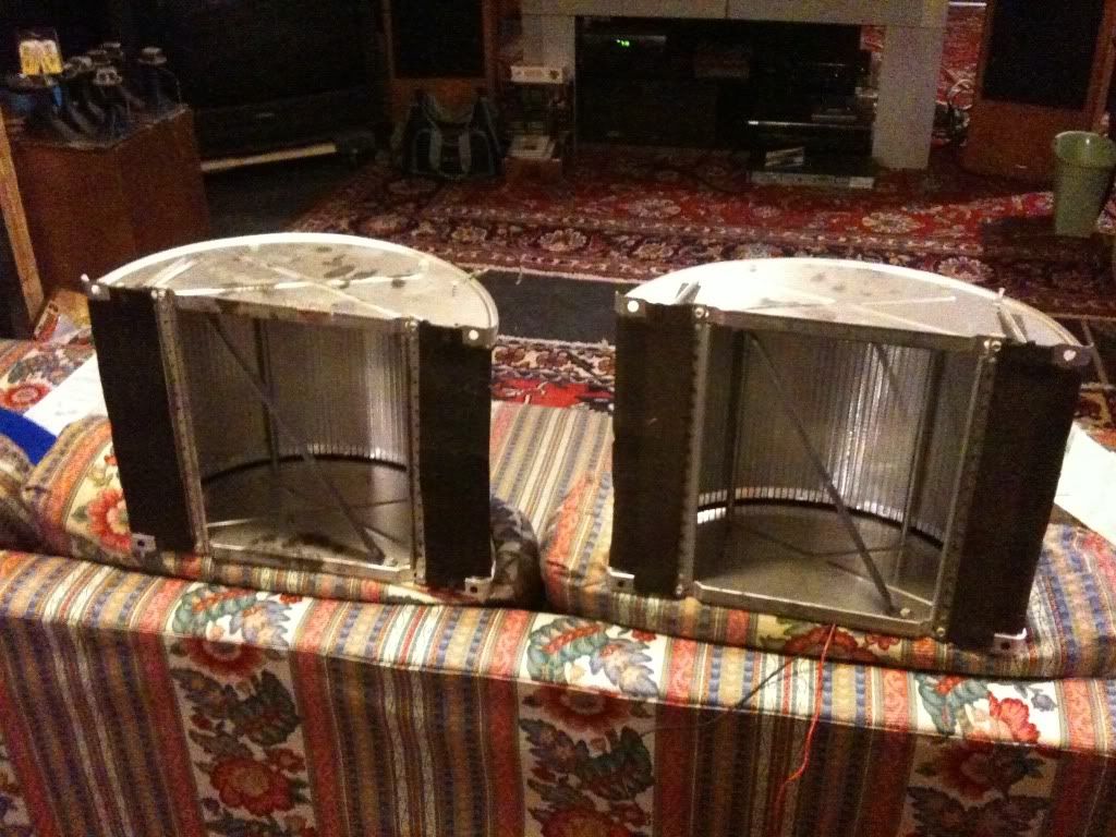
Does anyone have any Idea if the metal-framed 1/2 cylinder tweeter/ speakers were used in production product, or were they internal prototypes?

And if ANYONE can offer a link to a schematic for hooking them up, that would be great.

BRIEFLY looked at the electronics that came associated with these, and it seems to be a HV bias supply and cross-over / possible step-up transformers. Never seen anything similar, but that means nothing.

Will try and post some pictures tonight for the intrepid brain trust to weigh in on!
 
Some electrostats had only 2 wires. The ones in my Grundig console only have 2. It wires to an SE output stage. I think one wire goes to ground, the other to the plate but I may be wrong on that. I haven't spent much time inside of that and I haven't got a schematic for it.

You are correct, my blaupunkt had 2 on the sides, only 2 wires and ran in series from tweeter to tweeter- came off a separate tap from the opt.
 
Will have to hunt down some schematics.

And if ANYONE can offer a link to a schematic for hooking them up, that would be great.

BRIEFLY looked at the electronics that came associated with these, and it seems to be a HV bias supply and cross-over / possible step-up transformers. Never seen anything similar, but that means nothing.

Well -

Seek & ye shall find.

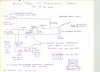
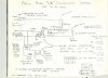
digging further into the pile O' data I picked up with these, I found these two schematics:

Version #1

attachment.php


Version #2 (?)

attachment.php


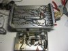
And here is the Bias (?) crossover (?) Thang: SEEMS like it is related to some part of the schematic above, but the only thing that matches up is the 10uf caps, but there are 12 of them (each can has two sections)

attachment.php


That HV / Bias PS on the right says 1180V - its a little hidden..

attachment.php


The center connection that is faded says "Membrane" I believe, corresponding to the marking to the cone shaped thing on the Schematic marked "Membrane & Frame"

attachment.php


I am still trying to wrap my head around how a single-ended electrostatic panel would work - rather than push-pull, is it repel - pull?
 

Attachments

  • Philco LS 36-1665 1.jpg
    Philco LS 36-1665 1.jpg
    51.5 KB · Views: 159
  • Philco LS 36-1665 2.jpg
    Philco LS 36-1665 2.jpg
    65.1 KB · Views: 157
  • IMG_2527.jpg
    IMG_2527.jpg
    61.4 KB · Views: 165
  • IMG_2529.jpg
    IMG_2529.jpg
    56.1 KB · Views: 159
  • IMG_2530.jpg
    IMG_2530.jpg
    60.6 KB · Views: 165
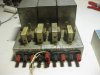
This does not seem to match the schematic above - resistors do not match, the DPDT switch shown for phasing is not where I would expect it, but there IS one in the power / bias supply, on the HV bias output (right side switch in photo) and I see clear R/L speaker terminals for the outputs, but what to make of the red/black one in the center marked 'Membrane' - I would think that for stereo, there would be two of these???? WFT? Captain Kirk?


attachment.php


Shot of one of the two transformers mounted in towards the center of the unit - but not marked A-8101 as noted on the schematic above - the two flanking ones are chokes, I believe.

These were described to me as prototypes straight from the Philco R&D zone, so....... does anyone know a site for Philco experts (will check above, I believe it was mentioned) - and any clue who Bill Greenwood was? His name is all over this stuff.

attachment.php


attachment.php


I'll try and trace out the as-built schematic of the units and at least test the HV supply - I love a good mystery. And I bet these things sound pretty cool, or alt least as cool as they look.

Does the concave or the convex face of the curved panels face the listener?
 

Attachments

  • IMG_2528.jpg
    IMG_2528.jpg
    80.1 KB · Views: 142
  • IMG_2531.jpg
    IMG_2531.jpg
    64.7 KB · Views: 137
  • IMG_2533.jpg
    IMG_2533.jpg
    49.9 KB · Views: 137
Any luck finding more on these speakers? I just picked up a pair. As soon as I receive them, I will be cleaning them up and repairing them.
 
Any luck finding more on these speakers? I just picked up a pair. As soon as I receive them, I will be cleaning them up and repairing them.

Not sure to whom that question was posed, but as for me who *was* looking for a set, I'm not looking for them any more. I trashed the Philco console and parted it out.
 
electrostatics

I remember when the old Olson Radio had 2" by 6" electrostatics for sale.
way back in the 50's. I was around 12. They worked on the output tube final voltage to work. Maybe 350V.
I bought a few and had an old really big am radio that I used to play am and eventually I hooked up a phono with a ceramic cart, and it sounded great.
One day I started trying to hook up the electrostatics by just hunting and pecking around the output tubes. I think it was push-pull. The tubes were simple ones like 83 or 45.
I made many misses but finally hit the output something or other, I think.
The sound was beautiful. They didn't last long due to the 350 or more volts.
The golden membrane was taking all the volts and fried if I turned it up too loud. I didn't know anything about resistors or caps. so the speakers didn't last long.

Paul
 
I have 4 smaller electrostatic tweeters made by Jensen that i pulled out of some units long ago. Cabinets were beyond hope and no amps to be seen.

They operate off of the B+ side of the amp and need at least 250 volts to operate-barely, but do come to life at 350 volts. The need for a capacitor is questionable since the Jensen design is essentially one large small value capacitor; the other connection goes to chassis ground potential. Great for attracting smoke and dust too.

For the Forbidden Planet speakers, maybe try simply placing a sheet of metalized foil (very thin window tint film) across the gap. or simply a thin film of polyester across the gap and then place some decorative expanded metal over the front of them that attaches to chassis ground. From the looks of the images, that seems all that is missing, especially if that is residual foam on eaither side on the flats.
 
Last edited:
Back
Top Bottom