

You are using an out of date browser. It may not display this or other websites correctly.
You should upgrade or use an alternative browser.
You should upgrade or use an alternative browser.
Philco J-1824 DW - need some help please
- Thread starter hypecat
- Start date



I uploaded the Philco J-1824 Sams schematic to my web page: http://www.audiophool.com/Philco.html
For the whole folder, email tbavis(at)rochester(dot)rr(dot)com
For the whole folder, email tbavis(at)rochester(dot)rr(dot)com
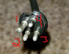
I think you may have the numbering reversed - usually the socket is clockwise when viewed from the bottom, plug is CCW. But I don't know if any information exists on these connectors.
Anyway, the audio loops through the reverb on that 5-pin connector on its way to the amp - so try connecting 1 to 4, 2 to 3 on that plug (I meant socket).
Anyway, the audio loops through the reverb on that 5-pin connector on its way to the amp - so try connecting 1 to 4, 2 to 3 on that plug (I meant socket).
Last edited:

Defeño
Active Member
Hey Hypecat! Nice looking set you got there. Kudos!
I'd highly recommend you get a volt/ohm meter. You can get a cheap one these days for about $20 and it'll make your life a WHOLE LOT easier. With an ohmmeter, you could easily figure out your plug pins, also figure out a lot of other stuff. You've got some great help here, but a VOM would make everyone's life much easier. This model, available at Home Depot, would certainly do the trick. Also, it's very handy to have one of these things around the house. You also might want to pick up some jumper wires with alligator clips on the ends. Those are quite handy too.
Cheers and good luck!
Kim G
Boston, MA
Where I remain eternally thankful for the help on various projects I've received on these pages.
Hmmm, I wonder which is correct?
Link to Tom's page: http://www.audiophool.com/Schem_A/Philco_J-1824_sch.gif


Link to Tom's page: http://www.audiophool.com/Schem_A/Philco_J-1824_sch.gif
Last edited:
I ran out and bought the Multimeter Delfeno recommended, can I use that to help determine which pins are which?
The picture on the yellowed paper is a photo from the inside of the cabinet, the digital copy is from your site Tom.... Aren't they both the manufacturers data?
When in doubt, I go with the manufacturer's data - though in this case, they don't show the pin spacing, so you can't tell pin 1. 1 & 4 are in / out from same cable, likewise 2 & 3.
The picture on the yellowed paper is a photo from the inside of the cabinet, the digital copy is from your site Tom.... Aren't they both the manufacturers data?
Defeño
Active Member
Now that you have a multimeter, you can easily check what's connected to what. So, for example, on the 5 pin plugs, you can clip one end of your VOM set to measure ohms to ground and the other end to the middle plug, and the meter should read very close to 0 ohms resistance. If the resistance is high, e.g., the needle doesn't move, then you've found a problem. You can repeat this on other parts of the circuit by clipping one end of the lead to whatever it's supposed to be connected to and then poke around (say on your plugs or jacks) to see where there's zero resistance and thus you can find the physical embodiment of what's printed on the schematic. I'm assuming you can read the schematic. If not, there are some basics, like the symbol for ground which is a triangular set of lines connected to a line (wire). Obviously everything should be unplugged while you do this.
I hope this helps. Good luck!
I hope this helps. Good luck!
Tom.... Aren't they both the manufacturers data?
Sams redrew their schematics - errors did creep in... but making things confusing, the manufacturer's drawing shows the pins on this connector equally spaced - they aren't - so you'll have to follow the circuit, not pin numbers. Convention is that jacks are numbered clockwise, on the back... but which is pin 1? Ohmmeter can tell you.


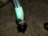
if you unplug it, use the house wire. If you don't unplug it use something small enough to work. Small gauge wire wound around the pins and then plugging the connector back in would get it done. A scrap of phone or network cable would give a bit of wire thin enough to do it that way.
Which pins jump together depends on how you do it. With the plug out, jump 2 to 3 and 1 to 4. With the plug in, try 1 to 2, and if that does nothing, try 3 to 4. Just let us know what you did and what happened either way.
Which pins jump together depends on how you do it. With the plug out, jump 2 to 3 and 1 to 4. With the plug in, try 1 to 2, and if that does nothing, try 3 to 4. Just let us know what you did and what happened either way.
Defeño
Active Member
I can do it "not" plugged in, just need to figure out what pin is what number, it's not very clear.
That's what your ohm meter is for. By referring to the schematic and noting things like wire colors, you should be able to attach an ohmmeter probe somewhere in the circuit that you know connects to, say, pin #1 of cable X. Then you probe the jack or the cable as appropriate with the other lead and when you find 0 ohms resistance, then you know you've found pin #1. Once you repeat this and find pin #2 or others, then you know which direction the numbers run and the next one is easier. I don't know if you've yet taken the electronics out of the cabinet, but if not, you're probably going to have to just hunker down and do that. Once done, then hooking up your probes becomes much easier. I hope you also bought the alligator clip patch cords as they make life much easier than just having the smooth probes of the VOM.
If you take this one step at a time, you'll be able to do it, even though it seems daunting. It's just a process of elimination. You've got some great help here. And we're all rooting for you.
Cheers,
Kim G
Boston, MA
Where against all odds, we managed to rebuild a pair of Heathkit W-5Ms this spring.
Defeño
Active Member
@hypecat. By the way, I'm inferring that you are in or around Minneapolis due to the reference to the place which did work on your console. I can recommend Tyler and Chelsea at tctubes.com, who are in St. Paul, as a source of tubes. Tyler also does repair work, and if you give up, he'd be a great person to call about getting your problem tracked down.
Cheers,
Kim G
Boston, MA
Cheers,
Kim G
Boston, MA
Last edited: