

You are using an out of date browser. It may not display this or other websites correctly.
You should upgrade or use an alternative browser.
You should upgrade or use an alternative browser.
Philips GA212 Toggle Switch Mod
- Thread starter huck1978
- Start date
tallesttree
New Member
Your mock-up appears to be correct!
In order to avoid RFI when the switch is operated, you may wish to add 2 x 22nF, X2 safety caps across the contacts: e.g. Example 1.
View attachment 1465389
Good Luck!
Alright Im just a little confused because according to a previous quote by gridleakrick on page 1 (referring to a switch that appears to be configured the same way) it should be wired with both transformer leads on either the left or right instead of top/bottom. I am very handy but this kind of thing really crosses my wires so to speak. So which way is right?
Cut the two wires off the old switch, strip them and wire them to the new switch. Use the two terminals on one side (either left or right--it doesn't matter which side). Wire color does not matter.
Last edited:

Hamish119
Active Member
If you're referring to this;Alright Im just a little confused because according to a previous quote by gridleakrick on page 1 (referring to a switch that appears to be configured the same way) it should be wired with both transformer leads on either the left or right instead of top/bottom. I am very handy but this kind of thing really crosses my wires so to speak. So which way is right?
you've misinterpreted what 's (correctly) stated.....Use the two terminals on one side (either left or right--it doesn't matter which side)...
The original switch is wired using 1 (of 2) pole(s). Your 'mock-up' uses 2 poles (a far superior solution - it's twice as good as a single pole...).
N.B. Not ALL switches have the same internal construction.
If you have doubts (or OCD) about the internal construction or how your switch operates, use your meter to check which 2 x pairs of terminals are closed when the switch is operated (it's DPST).
Or wire it as per your 'mock-up'.
Good Luck!
tallesttree
New Member
If you're referring to this; you've misinterpreted what 's (correctly) stated.
The original switch is wired using 1 (of 2) pole(s). Your 'mock-up' uses 2 poles (a far superior solution - it's twice as good as a single pole...).
N.B. Not ALL switches have the same internal construction.
If you have doubts (or OCD) about the internal construction or how your switch operates, use your meter to check which 2 x pairs of terminals are closed when the switch is operated (it's DPST).
Or wire it as per your 'mock-up'.
Good Luck!
Okay Awesome. Yes, that is what I was referring to. Thank you for clearing that up!
I really appreciate the help.
Dumb question, but is there a way to get into the 212 through the bottom or do I have to remove top/tonearm/sub platter/etc?
I am about to do the power switch mod but I'm hoping to avoid taking the whole top and subplatter off (trying to avoid breaking anything!!)
Thanks in advance
I am about to do the power switch mod but I'm hoping to avoid taking the whole top and subplatter off (trying to avoid breaking anything!!)
Thanks in advance

Dumb question, but is there a way to get into the 212 through the bottom or do I have to remove top/tonearm/sub platter/etc?
I am about to do the power switch mod but I'm hoping to avoid taking the whole top and subplatter off (trying to avoid breaking anything!!)
Thanks in advance

J English
Super Member
Anyone on this thread have experience with a dead channel problem on a 312 table? I have checked wire continuity all of the way from the headshell slide to the end RCAs, and can't find a problem. Is there a usual spot that the +/- wires tend to short together? Right channel is strong, left channel no sound and just a slight hum.
thank you very much for this thread! new member today . got this today for nothing (312)yup the switch. also got a rabco ST4 which i read somewhere is called something else.
again thanks!
you folks sound very knowledgeable
ps. i'd love to drop this off somewhere (Boston Ma.)
as my soldering skills....haha
again thanks!
you folks sound very knowledgeable
ps. i'd love to drop this off somewhere (Boston Ma.)
as my soldering skills....haha
Performed this fix... works excellent... used these:
https://www.amazon.com/gp/product/B07GN1YR2V/ref=ppx_yo_dt_b_asin_title_o09_s00?ie=UTF8&psc=1
Had to use my dremel with cut wheel to trim slots into metal tabs. Also, so switch would work correctly with enough room to push up and down when installed, had to trim off top nub on plastic shaft and very slightly adjust leftover shaft nub & indent line so switch cap would fit onto it ( I broke one shaft in the cap when adjusting so glad I had more switches). Note: Picture below shows test fit of cap on shaft before I cut top nub off to allow it to sit lower ... so switch would function correctly once installed in plastic holder.
Can confirm wiring to the two terminals on one side of new switch is correct. Note: Upon reinstall, put screws into assembly before moving into place as it's hard to get the screws into the holes once put in place.. you can then tighten down from there.
Works perfectly and very solid. Thanks for the advice... Phillis 212 is working again !!!
https://www.amazon.com/gp/product/B07GN1YR2V/ref=ppx_yo_dt_b_asin_title_o09_s00?ie=UTF8&psc=1
Had to use my dremel with cut wheel to trim slots into metal tabs. Also, so switch would work correctly with enough room to push up and down when installed, had to trim off top nub on plastic shaft and very slightly adjust leftover shaft nub & indent line so switch cap would fit onto it ( I broke one shaft in the cap when adjusting so glad I had more switches). Note: Picture below shows test fit of cap on shaft before I cut top nub off to allow it to sit lower ... so switch would function correctly once installed in plastic holder.
Can confirm wiring to the two terminals on one side of new switch is correct. Note: Upon reinstall, put screws into assembly before moving into place as it's hard to get the screws into the holes once put in place.. you can then tighten down from there.
Works perfectly and very solid. Thanks for the advice... Phillis 212 is working again !!!
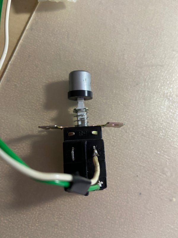
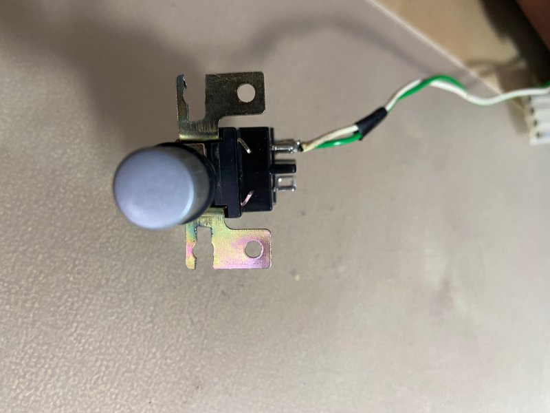
Last edited:

RamJacCorp
New Member
Hi, all. I dug out my old GA222, only to discover the infamous failed power switch. As suggested in this thread, I ordered an AT computer power switch to replace it, followed all of the instructions on the thread here (wired the two power leads to the top 2 terminals, the brown lead to the bottom left, and the blue lead to the bottom right), and hooked it up. The platter is spinning at about 1000 rpm! I don't know what could be causing that. Does anyone have a clue how I can troubleshoot, or should I abandon hope?
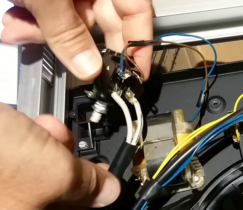
Last edited:
Hello Rick and all who are replacing the switch on the GA-212
I just finished completing the replacement and have one comment.
In addition to Rick's excellent explanation and photos, my GA-212 had 4 wires connected to the switch. From the button facing up, they are horizontal, 2 top and 2 bottom.
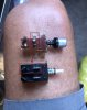
With the new switch, the top 2 wires connect vertically to P1 side of the switch and the bottom 2 again connect vertically to the P2 side. See my edited photo to see what I mean
Thanks again Rick for the excellent work!
Bob
I just finished completing the replacement and have one comment.
In addition to Rick's excellent explanation and photos, my GA-212 had 4 wires connected to the switch. From the button facing up, they are horizontal, 2 top and 2 bottom.
With the new switch, the top 2 wires connect vertically to P1 side of the switch and the bottom 2 again connect vertically to the P2 side. See my edited photo to see what I mean
Thanks again Rick for the excellent work!
Bob
Attachments
Last edited:

tony ismaas
New Member
Hi - as someone tackling the dead switch issue on my recent 212 purchase can you explain the suggestion for the caps? Is this to avoid an electrical click when switching?Your mock-up appears to be correct!
In order to avoid RFI when the switch is operated, you may wish to add 2 x 22nF, X2 safety caps across the contacts: e.g. Example 1.
View attachment 1465389
Good Luck!

mel.dev
New Member
Hello, I am currently repairing a a Phillips GA 222 with a broken on off switch. It seems like this fix will be applicable for this device as well but wanted confirmation of this. Do you know if this also works for 222?Here is how to modify the mounting ears of the new switch. Make sure the slots are wide enough to easily slide the screws in.
Push the knob onto the new switch before you mount it in place.
Cut the two wires off the old switch, strip them and wire them to the new switch. Use the two terminals on one side (either left or right--it doesn't matter which side). Wire color does not matter.
Hope this helps to resurrect some Philips 212 and 312 turntables.
Rick

Several possibilities.how do you fix the touch 45 and 33 buttons i have to keep my finger on them for them two work anyone have this issue any help wouod be much apreciated thanks in advance Mark
Question - were they working, and did you do anything recently.
Commonest cause - incorrect light bulbs. Original were 6 volts 50 mA (or 6.3 volts 50mA) and I believe 1-- mA for the stop bulb (find a service manual). If you put in 47 or 1847 or other bulbs that will fit, circuit won't work right. Also, check the stop light also.
Recent cleaning? The circuits work by small levels of resistance (like your finger tip) between the two metal rings for the logic to see it. Glass cleaner or any other cleaner will also cause the circuit to malfunction. Make sure that the switches are completely dry between the two bands. (Windex is pretty easy to dry - stronger cleaners take more time and drying to work correctly.)
Could be issues in the logic circuits. You didn't mention which table you had. 212 and early 312 (and 209) used light bulbs. Later 312 used LEDs, and don't have light bulb issues.