jmmani2
New Member
First time poster and wishing I had thought to look here first. I’m 39 and got into vintage audio about two years ago. I’ve repaired a couple of turntables and a few sets of speakers. This summer I found a really nice SX-737 for a great price. Everything checked out and seemed to be working except the phono (sound on right channel but only static and pops on left).
I watched YouTube videos for two months before deciding to tackle replacing the capacitors and transistors. I bought a repair kit online from a highly reviewed seller and swapped everything out today. My first test after the repair showed that I actually made everything worse and now I have nothing on either channel.
Here’s the real kicker. Not once in my research did I find a warning against unwrapping the wire on the pins. So, like the newbie I am, to better access the solder joints I unwrapped all the pins to work and then rewrapped them to reinstall the phono board.
Won’t you know that the first post I found on audiokarma while trying to figure out what I might have done wrong was a post warning about the grave mistake of unwrapping wires from the pins. Sigh…
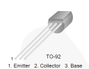
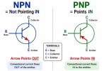
So, here I am unsure of how to proceed. I feel pretty confident that I replaced on the transistors and capacitors correctly. The new transistors were ECB, so I knew that they would go in differently than what I was removing. I don’t think my solder joints are awful for someone that has only soldered a handful of things. And I matched all the capacitors to the originals and the markings on the board.
I believe at least one of my issues is now in the wire wrap since I essentially broke the air lock that originally existed. What are my steps moving forward? Can I solder the rewrapped wires to the pins to create a better connection? Cut, strip, and use the wire wrap hand tool I got off Amazon to do try again? I have no techs nearby that I’m aware of and I’m generally a really handy guy and rarely need to call in professional help for repairs around the house. Admitting defeat here will hurt but I’m not above it if needed. I’d like to think I can solve this.
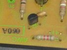
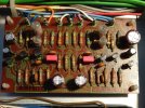
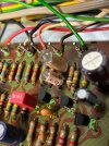
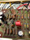
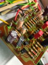
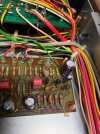
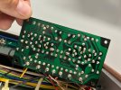
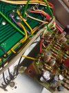
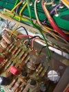
I’d appreciate any and all advice. I’ve attached some pictures of the board in its current state in case anyone can diagnose my issue from a picture.


I watched YouTube videos for two months before deciding to tackle replacing the capacitors and transistors. I bought a repair kit online from a highly reviewed seller and swapped everything out today. My first test after the repair showed that I actually made everything worse and now I have nothing on either channel.
Here’s the real kicker. Not once in my research did I find a warning against unwrapping the wire on the pins. So, like the newbie I am, to better access the solder joints I unwrapped all the pins to work and then rewrapped them to reinstall the phono board.
Won’t you know that the first post I found on audiokarma while trying to figure out what I might have done wrong was a post warning about the grave mistake of unwrapping wires from the pins. Sigh…
So, here I am unsure of how to proceed. I feel pretty confident that I replaced on the transistors and capacitors correctly. The new transistors were ECB, so I knew that they would go in differently than what I was removing. I don’t think my solder joints are awful for someone that has only soldered a handful of things. And I matched all the capacitors to the originals and the markings on the board.
I believe at least one of my issues is now in the wire wrap since I essentially broke the air lock that originally existed. What are my steps moving forward? Can I solder the rewrapped wires to the pins to create a better connection? Cut, strip, and use the wire wrap hand tool I got off Amazon to do try again? I have no techs nearby that I’m aware of and I’m generally a really handy guy and rarely need to call in professional help for repairs around the house. Admitting defeat here will hurt but I’m not above it if needed. I’d like to think I can solve this.
I’d appreciate any and all advice. I’ve attached some pictures of the board in its current state in case anyone can diagnose my issue from a picture.