

You are using an out of date browser. It may not display this or other websites correctly.
You should upgrade or use an alternative browser.
You should upgrade or use an alternative browser.
Phono Board SX-737
- Thread starter jmmani2
- Start date
If you like, start with this thread and read everything at post #2 carefully,
1. Basics, tools and how to start
Let’s start with the work, but always keep in mind, I had the second SX-737 sitting next, as a kind of master copy if I run into problems and needed a recheck.
Tools used beside the standard soldering stuff:
· DBT
· I use 4 DMM (very helpful when adjusting Offset and bias at the same time), a decent digital meter should have a diode test function
· Smartphone, to take hundreds of pictures, mainly before and during the work, MACRO function is quite handy
· LCR tester mega 328 (my every time saver if I need to...
Let’s start with the work, but always keep in mind, I had the second SX-737 sitting next, as a kind of master copy if I run into problems and needed a recheck.
Tools used beside the standard soldering stuff:
· DBT
· I use 4 DMM (very helpful when adjusting Offset and bias at the same time), a decent digital meter should have a diode test function
· Smartphone, to take hundreds of pictures, mainly before and during the work, MACRO function is quite handy
· LCR tester mega 328 (my every time saver if I need to...

jmmani2
New Member
I appreciate it. I wish I would’ve found this forum 48 hours ago.If you like, start with this thread and read everything at post #2 carefully,
1. Basics, tools and how to start
Let’s start with the work, but always keep in mind, I had the second SX-737 sitting next, as a kind of master copy if I run into problems and needed a recheck.
Tools used beside the standard soldering stuff:
· DBT
· I use 4 DMM (very helpful when adjusting Offset and bias at the same time), a decent digital meter should have a diode test function
· Smartphone, to take hundreds of pictures, mainly before and during the work, MACRO function is quite handy
· LCR tester mega 328 (my every time saver if I need to...

you were shown pinouts. i explained the symbol. you were told to look at datasheets.I appreciate everyone’s help. If anyone has a nice tutorial or video on how to read transistor schematics and install them correctly, feel free to link it. I’m going to go reevaluate and figure out why I was so confidentially wrong.
what else is there?
just apply yourself. it takes time.

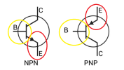
jmmani2
New Member
Yes sir. I’ve clearly misunderstood something along the way. I even had instructions with a diagram from the seller. Like I said, I grossly misinterpreted something. Just trying to go at it a different way before I remove these misplaced transistors and try again with new ones. I really do appreciate all the help.you were shown pinouts. i explained the symbol. you were told to look at datasheets.
what else is there?
just apply yourself. it takes time.
jmmani2
New Member
Between the advice, the step by step guide thread, the diagrams, the photos, and the words of encouragement, I think I’ve got what I need to keep learning and try this again once my new transistors come in. I’ll send pictures before I solder them into place.
Again, thank you everyone for all the help. I’ve never done anything quite like this, so it was awesome to have a community so willing to jump in and give constructive advice. Much appreciated!
Again, thank you everyone for all the help. I’ve never done anything quite like this, so it was awesome to have a community so willing to jump in and give constructive advice. Much appreciated!
jmmani2
New Member
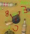
Is this mark up an accurate label of what you’re describing?insert them like this
note the marking under the transistor in my pic.
you can see the emitter on the left-with the arrow.
the base is the flat line on the right
you can not see the collector-slanted line opposite the emitter
View attachment 3831092
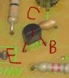
yes.Is this mark up an accurate label of what you’re describing?
View attachment 3831780
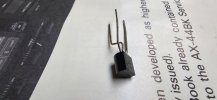
these 3 transistors
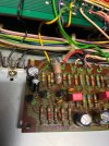
will install in this direction

these 3 transistors
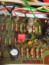
will install in this direction
can you follow that?
in this situation, i put a little kink in my leads instead of bending the collector like you did. don't feel bad, ALOT of people just flex the leads and cram it in the hole. i've done it. i will probably do it again. it just makes for a nicer job like this.

jmmani2
New Member
Super helpful. Thanks for taking the extra time. I don’t know what had my thinking off, but tonight while reviewing your pic from earlier, something clicked and I realized the issue. Feel like a dummy now, but that’s how it goes sometimes.yes.
these 3 transistors View attachment 3831792
will install in this directionView attachment 3831793
these 3 transistorsView attachment 3831795
will install in this directionView attachment 3831796
can you follow that?
in this situation, i put a little kink in my leads instead of bending the collector like you did. don't feel bad, ALOT of people just flex the leads and cram it in the hole. i've done it. i will probably do it again. it just makes for a nicer job like this.
View attachment 3831798View attachment 3831799
Great tip about the kink in the transistors also!
it happens. just gotta shrug it off and move on. i do MUCH dumber stuff than this but i still take time to install a cap or transistor in backwards once or twice a year.Feel like a dummy now, but that’s how it goes sometimes.
build a dim bulb tester if you plan to keep tinkering.

bayernfan
Active Member
Use this as a guide for future work on your 737:

 www.olegvintageaudio.com
Pioneer SX-737 Receiver Restoration
Pioneer SX-737 Vintage Receiver Restoration
bayernfan
Active Member
it happens. just gotta shrug it off and move on. i do MUCH dumber stuff than this but i still take time to install a cap or transistor in backwards once or twice a year.
build a dim bulb tester if you plan to keep tinkering.
About as easy as it gets if you have a Lowe's nearby.
jmmani2
New Member
Thanks for the encouragement!it happens. just gotta shrug it off and move on. i do MUCH dumber stuff than this but i still take time to install a cap or transistor in backwards once or twice a year.
build a dim bulb tester if you plan to keep tinkering.
it happens. just gotta shrug it off and move on. i do MUCH dumber stuff than this but i still take time to install a cap or transistor in backwards once or twice a year.
build a dim bulb tester if you plan to keep tinkering.
Warning, kinda long story about my recent screwup!
I'm embarrassed at what I've done this last week. I've been trying to get my old CD Player working again. I'm not sure how it got in such disarray but I believe it started with a replacement belt that was too tight causing too much current through the IC that drives the motors, causing it to go bad. This IC is driven by opamps.
I messed up a couple of opamps by swapping from another location only to fry 1/2 of it. The IC it drove has 6 transistors in it and it checked fine on my meter just as 6 transistors would. I put it away for close to 10 years. Recently, I wanted to see if I could get it going. It fried another opamp. I figured out that if I removed the IC that it drives, the opamp would survive. I replaced the opamps and the IC that they drive. It was up and running, playing CDs perfectly. Then it stopped working.
I lost the 5 V power supply which comes from a 12V power supply. It popped an IC protector (fuse). I replaced it and it was working again. Shortly after, it popped that IC protector again. I decided to clip my meter across the leads in mA mode and see what kind of current draw there was. It came back to life and current draw was around 100mA iirc. Then It stopped working again. So I had 12V going to the open IC protector and I thought I was supplying 12V to section where 12V becomes 5V. I checked those transistors, diodes, resistors and they seem fine. After scratching my head for about a week, I decided to try a different meterto measure current draw. It came back to life! My meter popped a 250mA internal fuse! So at this point I'm thinking something is under the PCB causing a short. I lifted it out and replaced the IC protector but couldn't find anything shorted....until I was reassembling. I knew a ground wire was supposed to be under a screwhead. It was not there when I removed the screw! It was under the PCB causing an imtermittent short!
I really don't understand why the original IC was eating opamps. I think when it had voltage applied, it was breaking down and sending 12V to the output on the opamp, causing it to fail. When the opamp would fail, there was just under 12V output from the opamp causing the spindle motor to run like a bat out of hell when it should have been stopped.
Watchout for rouge wires!!
Watchout for rouge wires!!
i can definitely one up you.....
pioneer sa-7100. i was replacing the across the line cap. i made sure my dbt was turned off. i even eyeballed the outlet and made sure the unit was not plugged in to the dbt.
i'm good. get one leg unsoldered. go at the other leg. WHOMP!!!!. my soldering iron touched the pins on the backside of the ac convienience outlets and blew a hole in the shaft of my iron.
my failure was that i did look another 12 inches past my dbt. had i done that, i would have clearly seen the unit plugged into the wall.
MAKE SURE THE UNIT IS UNPLUGGED! make sure you are awake. make sure you are not groggy.
i had tunnel vision. the wall outlet and dbt are in the same view. they are right there. how i did not see that cord plugged escapes me.
things could have ended up very differently if i held my iron like this chick
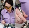
note: do not hold your iron like this chick.

bayernfan
Active Member
Nice, you're well on your way. Do you plan on doing more boards on the 737?Glad it wasn’t worse! Just finished my DBT by the way