

You are using an out of date browser. It may not display this or other websites correctly.
You should upgrade or use an alternative browser.
You should upgrade or use an alternative browser.
Picked up a Rough KX-100 Tube Amp - Will need some guidance
- Thread starter Tim D
- Start date

Look up @ mouser "220uf 350v radial capacitor". The results page will give you a list in a scroll page. You can also scroll LEFT and RIGHT using the bar on the bottom of the page.
If using Winblows, Holding CTRL and rolling your mouses wheel back and forth you can vary the size of the font so if the page is huge you can bring it down to size, or just scroll Left and Right.
The sizes are in the specifications on the right side of the page also.
If using Winblows, Holding CTRL and rolling your mouses wheel back and forth you can vary the size of the font so if the page is huge you can bring it down to size, or just scroll Left and Right.
The sizes are in the specifications on the right side of the page also.

Tim D
Super Member
Thanks guys. Zeroing in on a set of electrolytic replacements. Your feedback on how to find the sizes is helping. While ordering I'm trying to work up a more comprehensive parts list to save on shipping. I've been digging through the parts lists and various threads and I'm trying to determine what changes I might make to this KX-100. I've got a few questions.
I've seen mentions of grid resistors changed from 330k to 220k ohms, But on the KX-100 the bias is not adjustable. Should I be changing the bias circuit on the KX-100 to be more like the X-100-B to make the bias of the output adjustable if I make that mod? (Perhaps make the change to make each output tube's bias individually adjustable per the X-100-B restore thread? I'd hate to put in the grid resistor change just to find out that I've really messed up the bias.
Also I see several threads adding in a 10 ohm resistor in the cathode circuit to measure current through the tube. How are these used to measure the current? Use a volt measurement and a calculator with ohms law? (Sorry if this is obvious or mentioned somewhere.)
I see where some are replacing the coupling caps from 0.047 uF to instead be 0.1 uF. Any thoughts on why? What type of cap should I look for? Film maybe? Is this only for the output stage or through out everywhere there is a coupling cap that is 0.047 uF?
BTW, thanks for all your help.
Tim D
Super Member
Discovered differences between the KX-100 and X-100-B.
Just as a side note. I've been digging through the diagrams and parts lists for the KX-100 and the X-100-B. I have diagrams for two different versions of the X-100-B but I can't find any electrical differences in the two versions of the X-100-B. Here are the differences between the KX-100 and X-100-B that I've found so far.
1. The X-100-B has a single cap added to the power supply where the secondary of the power transformer joins the two diodes. This is listed as C33 which doesn't exist on the KX-100 and it runs from that junction to ground. It's listed as a "Molded 0.01 uF, 20%, 600V". I'm wondering if it is some kind of filter for high frequency (RF maybe?) that might come in on the line? Useful at all? [EDIT: Found a thread that talks about this extra cap from dcgillespie. It's in post #51 1st paragraph of this thread: http://audiokarma.org/forums/index.php?threads/fisher-kx-100-x-100-b-restoration.572641/page-3]
2. Values for C23 and 24 were changed from 100 pF (KX-100) to 180 pF (X-100-B). These are in between the two halves of each of V5 (and V6). I.e. Between the Plate of the first half and the grid of the second half. These caps go to ground. Same reasoning? Is this a filter to reduce RF interference? Is this useful at all?
3. The rest are relating to the difference in the bias circuits with the KX-100 (fixed) and X-100-B (adjustable - with a single adjustment for the entire output stage).
a. R69 (in the X-100-B) has been moved to where R70 was located (in KX-100).
b. R70 (in the X-100-B) has been added to a new location and is now a 5K pot.
c. R76 has been added in the X-100-B in the location where R69 was in the KX-100.
That's all I've found so far and it might be complete as I've gone through the entire parts lists of all 3 versions. (Assuming that there were no other part relocation's excepting for what I've already identified in the bias circuit for the output stage.)
Last edited:
Fisher amps using 7591's with Cathode Bias'ing can use the 330K with no problem. The answer lies with the 7591 spec's. With Fixed (adjustable) biasing, the max grid resistor is spec'ed for 300K maximum. in Cathode Bias, the maximum grid resistor spec is 1megohm. So 330K is ok as you have Cathode Bias.
Cathode resistors are placed connected to the tube socket tab,and the wire that was removed from the socket tab. It IS NOT GROUNDED as in Fixed bias. You put a probe on each end of the resistor and read DC VOLTS, and then convert to ma.
As you aren't changing the grid return resistors there is no need to change the value of the coupling caps. Leave the value the same but bump up the voltages from 250 and 400 to 600 or 630. Use film caps (orange drops or Cornell Dublier DME's are fine) Russian K40y or K42Y are fine too but the cases are metal and due caution is needed to keep the case from grounding resistors or other leads.
Go with what is in the unit and on the KX-100 schematic. Dave could give you the reasons for the differences to the caps and resistors but I think they are changed due to the differences in the Bias circuits.
Larry

pdm4606
Super Member
I would replace the output tube sockets. Many years ago I built a KX-100 and it worked fine. However for some reason the output tubes started arching at the pins. I mean arching from the tube pin to the socket connector. I caught it a few times. Once it got so bad that the tube was actually welded into the socket. I could not remove it. I gave the amp away and bought a solid state amp.
I got a Marantz 1060 and never looked back. I still have the 1060 and just did a cap. replacement.
I got a Marantz 1060 and never looked back. I still have the 1060 and just did a cap. replacement.

fred soop
Super Member
Look up @ mouser "220uf 350v radial capacitor". The results page will give you a list in a scroll page. You can also scroll LEFT and RIGHT using the bar on the bottom of the page
......
The sizes are in the specifications on the right side of the page also.
The earlier implication was that Mouser only had the size info in the grid after a selection, but after checking, I see that they also have size in the pulldown menus, same as DK.
My dislike of Mouser goes back to the 1980s. They had a $25 minimum order. It would take 30 days to ship 1/3 and back order 2/3. After 60 days, they would ship the second 3rd and cancel the remainder. The remainder was not enough to meet the $25 minimum on a reorder. After they did this repeatedly, I dumped them. Things have changed, I have ordered from them in recent years, but the memory lingers on.
Like my dislike of the local Chevy Dealer for the last 25 years. I bought a 89 G-20 conversion van new. At 32000 it was sucking up coolant at the rate of a gallon a week. Took them 6 months to accept there was a problem. No smoke from the tailpipe, No Antifreeze in the oil (dipstick only had oil on it), But the cap was sludgy with light brown oil that had seen moisture. I was changing the oil every 2 weeks at that point. They finally filled up the coolant tank, ran a tape over the cap, and down the side. I was to mark the tank and tape daily before starting up in the morning then bring it in. 4 days later, the tape was checked, and ok'ed by the Service Mgr. They took the van and it took 3 weeks for them to tear down the engine, then discover that the block had a crack in the coolant wall between #5 and #7 cylinders right above the lifters. Coolant was weeping out when engine was running and hot. Turn off the pressure would push out coolant which boiled off. So they ordered a new block for a 305. Took 2 months for that. It took another 2 weeks after the block showed up. They paid for it all under warranty. I never got offered a loaner. GM Corporate got a nasty letter for this one.
Then there was the battery in my 95 Astro. They put in the battery 6 months before, and it developed 2 dead cells. It had cell caps so I took my DMM and checked each cell. #2 had 6v and #5 had 9v all the rest were fine after an all night 2 amp charge. Started up the astro and took it up to the Dealer. They take it in and 4 hours it's back out. They turn it off. I went in and did paper work and came back out. NO START! WTF???? Take my meter and open the hood. Pulled the caps. Checked all the cells. Same as this morning. I went into the Service area and cornered the Service MGR. He makes 2 phone calls real quick. So the Service manager, lead parts changer, and the GM of the dealership show up with the tech who checked this van .I explain the problem as I did to the Service writer and what i had done overnight with the charger, and why I'm raising so much hell now as the same dead battery is still in it, and results with my $4.95 Harbor Freight Meter. The Lead tech comes out with his GM Approved whizbang does everything except zap the dingle balls off yer backside battery tester. He hooks it up and tests the battery, it reads good at 11.5V.
"Put a load on it and watch the voltage drop, then unload it and watch the voltage rise. Everyone looks at me like I had 3 heads and the ServiceMGR said the $800 Whizbang meter doesn't load the whole battery. "Then how the hell do you determine if a battery is good or bad"? If the voltage is below 10.5Vafter charging it's bad. "OK, We'll turn on the headlights for 3 minutes and watch the drop then turn them off and watch the recovery." So I turned on everylight in the whole van. The voltage dropped down to 6V within 15 seconds and then dropped down to 5v after 2 minutes (I cut the load test short). Turned off the load and it took 5 minutes for it to finally top off at 9.8V. The GM looks at everyone and told them to put a new battery in it and get me out of there in 30 minutes or less. Took them 15 minutes.
What galls the hell out of me is they have all these fancy tools that they either don't know how to use or they use them incorrectly. The Service MGR should have know how to check battery cells, but..........
Last time I ever planted my feet or drove in to them. And I'll never go back, even tho I have a 2002 S-10 quad cab and a 95 GMC Jimmy. I'll go across town to another dealer.
Now back to the KX-100 problems.
Tim D
Super Member
Ok. I'm not going for a major mod in the near term. Just adding in the in-rush limiters (CL-80's), fuse, and replace the electrolytics. I've got the caps on order. I'm still looking for a shell to stuff for C1. I don't care if it looks like the original paper can or an aluminum can. Max height is 3.25" - I'm assuming no higher so that the finished unit can go into a case someday. I also have to come to a decision for the output tubes.
I've received some parts from an AK friend today as well. (Couple of switches, knob, fuse cap, and some brights from the parts list I was seeking.)
The cleaning is going so-so. I've deoxit'd the switches and pots. I've managed to go over the whole chassis once with the Krud Kutter. It looks better, but not great. I'm now going back over it with Brasso to see how much I can really clean it up. The clean-up is slow going. I'll post some pics tomorrow.
Last edited:
IIRC C1 is part of the voltage doubler and insulated from the chassis. It has approx 200v on the outer shell which is why it's covered with a cardboard shell. Please DO ensure the cardboard cover is reinstalled on the replacement cap.
Tim D
Super Member
IIRC C1 is part of the voltage doubler and insulated from the chassis. It has approx 200v on the outer shell which is why it's covered with a cardboard shell. Please DO ensure the cardboard cover is reinstalled on the replacement cap.
Wow. 200V on the shell? That would be a big ouch. I don't have the original C1. Someone replaced it with a vinyl sleeved cap that wasn't mounted properly. It had actually fallen off. I'll do a post on BT to see if anyone has an old one available that I can re-stuff.
Tim D
Super Member
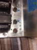
Ok. I've spent a lot of time working on the corrosion and pitting. It looks better to the eye, but for some reason pictures don't pick up the improvement. It's not going to get to a visually pleasing look ever unless I totally strip the chassis and that is a bridge too far for me.


Tim D
Super Member
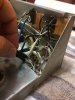
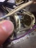
I've been chasing a mystery on the audio source input selector switch (S1) on the diagrams. Someone had disconnected two wires from the back disk on S1 and taped them together. The lugs where the wires sat were lugs 1 and 2 on the back disk of S1. It joined a purple and green wire which are identified in the assembly manual. I can trace it out. It made me think that maybe there is something wrong with S1, but I did a continuity check and it closes in on all selections except for the tape head. Not sure why it closes in for most of the selections as the wires seem to connect to the phono inputs, so I'd have thought it would only close in on the phono selection. I'll do some more digging through the diagrams. Worse comes to worse, I can put the wires back to where they belong and test it out when I get the amp up and running. This is in the low signal path.



Tim; Way back when car's were powered by feet and dinosaurs were the main source for mechanical power (1950's) tape decks didn't usually have preamps on them. Most of them were playback only and commercial tapes were the thing. (Only nerds who recorded their own tapes used decks with preamps and they were high end stuff then). The output's were directly tied to the heads. So the tape heads required a pre-amp similar to magnetic phono input's. TAPE HEAD input is a low level signal that is amplified and equalized to what became the NAB equalization. Most preamps and receivers had this input to accomodate those tape decks without pre-amps. Those tape decks with preamps internally, used the REC and Tape mon PLAY (TAPE MONITOR) line level input. If you put a phono in the tapehead input it will sound slightly different than the phono input. But if you put the inputs from say a TEAC A4010 you'll get overwhelming distortion, because the input level is 100-200% higher than required, and quite possibly can blow out the circuit.
It's possible the previous owner disabled the TAPEHEAD at the switch just so the inputs couldn't be used.
Larry
It's possible the previous owner disabled the TAPEHEAD at the switch just so the inputs couldn't be used.
Larry
re; aesthetic's. I've got a couple that look worse than that and they work quite well. Clean up and paint the transformers, and polish the tube shields, along with the can caps (or just wax the hayseeds). That will take their eye's off the "patina" for a while (3-5 seconds, maybe). Just clear coat it and leave as is for a rat rod look. You're not going to get it much better if at all by stripping the chassis. You'll still have the pit's and scarring, that you'd either leave alone or fill with bondo or lead, then paint or chrome. You could end up making a new chassis and lettering it from scratch, for what? You won't have the original chassis and it's "war wounds". It's a SURVIVOR! Let it show off it's battle wounds against mice, rain, and general neglect that you stopped.
Tim D
Super Member
re; aesthetic's. I've got a couple that look worse than that and they work quite well. Clean up and paint the transformers, and polish the tube shields, along with the can caps (or just wax the hayseeds). That will take their eye's off the "patina" for a while (3-5 seconds, maybe). Just clear coat it and leave as is for a rat rod look. You're not going to get it much better if at all by stripping the chassis. You'll still have the pit's and scarring, that you'd either leave alone or fill with bondo or lead, then paint or chrome. You could end up making a new chassis and lettering it from scratch, for what? You won't have the original chassis and it's "war wounds". It's a SURVIVOR! Let it show off it's battle wounds against mice, rain, and general neglect that you stopped.
Hey Larry, I like your direction - "war wounds". It was just me being "anal" about making it look its' best. I'll scale it back to just do enough work to get the brown and black iron oxide off and to shine and wax it and call it done. I was wanting to get it good enough that I wouldn't need to hurry up and get a case for it. That just takes the pressure off.
Tim D
Super Member
Tim; Way back when car's were powered by feet and dinosaurs were the main source for mechanical power (1950's) tape decks didn't usually have preamps on them. Most of them were playback only and commercial tapes were the thing. (Only nerds who recorded their own tapes used decks with preamps and they were high end stuff then). The output's were directly tied to the heads. So the tape heads required a pre-amp similar to magnetic phono input's. TAPE HEAD input is a low level signal that is amplified and equalized to what became the NAB equalization. Most preamps and receivers had this input to accomodate those tape decks without pre-amps. Those tape decks with preamps internally, used the REC and Tape mon PLAY (TAPE MONITOR) line level input. If you put a phono in the tapehead input it will sound slightly different than the phono input. But if you put the inputs from say a TEAC A4010 you'll get overwhelming distortion, because the input level is 100-200% higher than required, and quite possibly can blow out the circuit.
It's possible the previous owner disabled the TAPEHEAD at the switch just so the inputs couldn't be used.
Larry
Hmm, thanks for the learn'n. I didn't know about the tape heads being low input because I never had an R2R in any of my systems. My first recording device was one of the early cassette recorders.
I'm going to go back and trace out the circuits a little deeper. I think I'm missing a point in how this switch is supposed to operate because the inner and outer disk on S1 seem pass connections back and forth with the phono stage in between for when phono and maybe tape head are selected. The hard part is that the diagram doesn't seem to tell you what is closed in for each position. I might have to draw that out myself via continuity checks to verify what it is trying to do.
This is fun!
Another thing to think about. Fisher normally grounded an input when it wasn't being used. So go from the ground connection on the RCA thru the selector also, not just the hot side. Fun stuff, eh???
So relatively old dogs CAN be taught new tricks huh???
So relatively old dogs CAN be taught new tricks huh???
