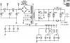
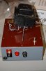
For B+ requirements, the preamp operates off of well filtered 150 vdc, with the B+ applied to pin# 7, and ground provided at pin# 9. The preamp requires 10 ma of power at this voltage level. When connected to an SA-260, this power is basically derived from a 300 vdc source from within that amplifier, which is then used to power the preamp through a 15K 2W resistor. 10ma of current flowing through this resistor produces a 150 volt drop, meaning that the 300 volt source has been reduced to 150 volts to properly operate the preamp. For your external supply, a transformer providing say 250-0-250 vac (for SS rectification) or 265-0-265 vac for tube rectification (a 6X4 would be fine) would work perfectly in a conventional full wave rectifier circuit to provide about 300+ volts of B+, that could then be filtered and dropped along the way down to 150 vdc for the preamp. If you use a tube rectifier, you power transformer will also require a 6.3 vac winding to power this tube's heater -- which could also be used to power the original pilot lamp as well if the original bulb is used. The high voltage winding of this power transformer would only need to be rated at a very low, say 25 madc, although a higher current rating would not hurt anything. If you use a tube rectifier, the 6.3 volt winding would need to be rated at 1 amp to handle the tube and pilot lamp.
Finally the AC switch of the 210 appears across pins# 4 & 5 of the preamp power cord. You could use this to turn the external power supply on and off. A fast-blo 3/4A fuse would protect both the high voltage power transformer, and the heater supply transformer.
With this basis then, it would then be a simple matter to use a C-R-C-R-C filter from the output of the rectifier, to filter and drop the B+ appropriately down to 150 vdc when the preamp was connected. The Cs could all be 40 mfd or so, and the Rs both 10K 2 watt resistors. These resistor values will be close, but could then be tweaked as needed to target 150 vdc when the preamp was operating. It would also be a good idea to place a 100K 1/2 watt resistor across the output of the filter, to provide for a bleeder to ultimately discharge the supply, should it ever be turned on without the preamp connected.
These components should all be readily available at the usual parts houses. I know this is not an actual schematic to build from, but if you follow these principles, you should be able to construct a suitable power supply for the 210 in relatively short order. Good luck!
Dave