• The move to the new server is done. There are some software and database maintenance updates in process. This has us passing the hat around to help out. We appreciate any donations. Seriously, even a dollar helps. The payment page may be found here - https://www.audiokarma.org/support.html

Pilot sp-210 power supply P-10 schematic

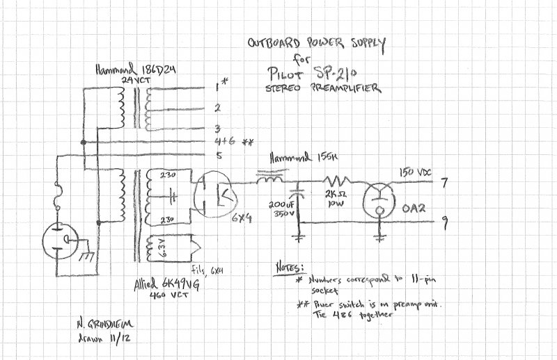
With Redboy's approval, here's the schematic he sent me a while back.


Redboy said he's built 2 of them with no issues.
 
Last edited:

Just wanted to add that I built one according to this schematic, and it does work. There is another thread about this PS in the DIY forum.
 
If your preamp has an indicator light and you'd like it to work, just extend the 6.3v winding to pins 10 and 11 of the supply...

SP210 indicator light.JPG
 
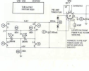
Hi, I know this is an old link, but in case someone in AK land is looking for a Pilot P-10 schematic in the future see pics below of unit and schematic. A friend brought over a Pilot SP-210 preamp that contains the P-10 power supply for me to recap. Before I gave it back I hand drew this schematic.
 

Attachments

  • Pilot P-10 Power Supply and Buffer Amp Schematic.jpg
    Pilot P-10 Power Supply and Buffer Amp Schematic.jpg
    97 KB · Views: 41
  • Pilot SP-210 and P-10 rear view.jpg
    Pilot SP-210 and P-10 rear view.jpg
    59.5 KB · Views: 38
  • Pilot P-10 side view.jpg
    Pilot P-10 side view.jpg
    98.4 KB · Views: 38
Makes it a lot more flexible. Stock it's just output from a 12ax7 but paired with the Pilot amps that power it that's fine. Not going to be more than about 3 feet away, and the load is known. Add the buffer and you can run basically anything at any reasonable distance.
 
Wading into an old thread here!

To build an external power supply should not be terribly difficult. Here's some information and guidelines that will help, from info taken from the 210 schematic, and that of an SA-260.

The heater supply for the 210 needs to be provided from the secondary of a 24 vac CT transformer, that can provide at least 1 Amp. It must have a CT connection, as the 210 employs a internal conventional full wave rectifier circuit to convert this AC power to DC for all of the filaments. On the preamp plug, the 24 vac is connected to pins# 1 & 3, while the CT is connected to pin# 2. I believe Radio Shack even sells an appropriate transformer to use for this purpose.

The pilot lamp on the 210 is connected to pins# 10 and 11, and requires 6.3 vac at 150 ma. If you are trying to keep your 210 all original, this will require a small (say 300 ma) 6.3 vac transformer on your external supply to power this lamp. Another option would be to install a similar base 24 volt version of the bulb, and simply use the AC power as provided to pins 1 & 3 for the heater supply to power this lamp as well. There is an additional option to power the original 6.3 volt lamp that will be explained in a moment.

For B+ requirements, the preamp operates off of well filtered 150 vdc, with the B+ applied to pin# 7, and ground provided at pin# 9. The preamp requires 10 ma of power at this voltage level. When connected to an SA-260, this power is basically derived from a 300 vdc source from within that amplifier, which is then used to power the preamp through a 15K 2W resistor. 10ma of current flowing through this resistor produces a 150 volt drop, meaning that the 300 volt source has been reduced to 150 volts to properly operate the preamp. For your external supply, a transformer providing say 250-0-250 vac (for SS rectification) or 265-0-265 vac for tube rectification (a 6X4 would be fine) would work perfectly in a conventional full wave rectifier circuit to provide about 300+ volts of B+, that could then be filtered and dropped along the way down to 150 vdc for the preamp. If you use a tube rectifier, you power transformer will also require a 6.3 vac winding to power this tube's heater -- which could also be used to power the original pilot lamp as well if the original bulb is used. The high voltage winding of this power transformer would only need to be rated at a very low, say 25 madc, although a higher current rating would not hurt anything. If you use a tube rectifier, the 6.3 volt winding would need to be rated at 1 amp to handle the tube and pilot lamp.

Finally the AC switch of the 210 appears across pins# 4 & 5 of the preamp power cord. You could use this to turn the external power supply on and off. A fast-blo 3/4A fuse would protect both the high voltage power transformer, and the heater supply transformer.

With this basis then, it would then be a simple matter to use a C-R-C-R-C filter from the output of the rectifier, to filter and drop the B+ appropriately down to 150 vdc when the preamp was connected. The Cs could all be 40 mfd or so, and the Rs both 10K 2 watt resistors. These resistor values will be close, but could then be tweaked as needed to target 150 vdc when the preamp was operating. It would also be a good idea to place a 100K 1/2 watt resistor across the output of the filter, to provide for a bleeder to ultimately discharge the supply, should it ever be turned on without the preamp connected.

These components should all be readily available at the usual parts houses. I know this is not an actual schematic to build from, but if you follow these principles, you should be able to construct a suitable power supply for the 210 in relatively short order. Good luck!

Dave

Dave, why does the SP-210 need a 1A 24VCT winding? It only has four 12AX7s. The Fisher 400C drove the heaters of four 12AX7s and two 12AT7s through a full wave rectifier from a 30V winding rated for somewhere in the vicinity of 0.43A. Likewise, the Ampex 960 and 1260 tape decks used a rectified 24VCT secondary rated around 0.45A for the heater supplies, and that thing was running four 12AU7s, four 12AX7s, and a 7025. Even the power transformer in the Pilot SA-232 amplifier, which was designed to power an SP-210 through an umbilical, is reported by Sams at .62A on the 23VCT winding. 1A seems like wild overkill in this instance compared to the handful of similar electronics that drove their heaters from 24-30V.

The Ampex 960 and 1260 PT has a HV secondary of somewhere around 290-320 VCT, it seems like it would be a solid choice for an SP-210 power supply unless I'm really not understand something about the heater supply for the four 12AX7s.

Also, either the stock Fisher 400C power supply or your reworked version of it seems like a good start for a power supply for the SP-210, from what I can see.
 
probably just duplicating the original design. Specs for the SA-260 transformer, the "not used" 23 VCT winding runs to the aux power socket to feed the SP-210. The SA-232 should have a similar winding for this purpose.

1760326900469.png


this is the power supply section inside the SP-210

1760327081887.png

+ 9.5 to -3 is 12.5 VDC which works out for a series/parallel set of four 12ax7. I have no idea why they designed it like this, seems more complicated than it needs to be in order to get 12.5 volts DC but someone must have had a reason for it.

600ma DC needs a little more than that on the AC side, so 1 amp would be about right.
 
probably just duplicating the original design. Specs for the SA-260 transformer, the "not used" 23 VCT winding runs to the aux power socket to feed the SP-210. The SA-232 should have a similar winding for this purpose.

View attachment 3613248


this is the power supply section inside the SP-210

View attachment 3613249

+ 9.5 to -3 is 12.5 VDC which works out for a series/parallel set of four 12ax7. I have no idea why they designed it like this, seems more complicated than it needs to be in order to get 12.5 volts DC but someone must have had a reason for it.

600ma DC needs a little more than that on the AC side, so 1 amp would be about right.

The Sams folder for the SA-232 reports the 23V winding for the SP-210 heaters as 0.62A, and THAT seems like overkill compared to the other units I mentioned, which also used DC rectification on a 24-30V secondary for the heaters driving more tubes than the SP-210.

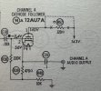
Just to make this really weird, there are some excellent photos of a P-10 on an eBay completed listing. For some reason that I don't understand, Pilot stuck a 12AU7 on the thing and ran the SP-210's output through it. The FA-540 tuner, in stand-alone form, has a 12AU7 and level pot that the console version lacks. But the P-10 doesn't have a level control, so I don't know what they were doing with that 12AU7. I'd love to see the insides, since the schematic seems to be completely non-available.

(Photos saved as reference from eBay, copyright belongs to the seller of that preamp.)
 

Attachments

  • Pilot SP-210 9.png
    Pilot SP-210 9.png
    471.4 KB · Views: 6
  • Pilot SP-210 11.png
    Pilot SP-210 11.png
    443.4 KB · Views: 6
  • Pilot SP-210 18.png
    Pilot SP-210 18.png
    498 KB · Views: 6
Dunno, maybe its overkill, but overkill is under-rated.

The 12au7 is a cathode follower on these, probably to make it more suitable with other power amps. I remember seeing either a schematic or just a good view of the inside of one to figure that out, though the fine points of it elude me.

**edit** oh, thats where I saw it. Post 25 above.
Nothing wrong with overkill. I just like to know what options I have that won’t melt down when transformer shopping.

Somehow I missed that post when reading this thread! I pulled the Sams folders for the SP-315 and 316/A from my box o’ schematics last night, they use 12AU7 cathode followers for both the line and tape outputs (as well as driving the VU meters!), so I figured that’s what it was for. Still, it makes for a strange place to mount it.
 
With Redboy's approval, here's the schematic he sent me a while back.


Redboy said he's built 2 of them with no issues.
Glad to see this schematic. Pretty sure I have one of the two PS that were built and long ago forgot what tubes go into it.

210_PS_Nate.jpg
 
Hi, I know this is an old link, but in case someone in AK land is looking for a Pilot P-10 schematic in the future see pics below of unit and schematic. A friend brought over a Pilot SP-210 preamp that contains the P-10 power supply for me to recap. Before I gave it back I hand drew this schematic.
For comparison, I looked at the SP-215, SP-216, and FA-550 Sams folders (the FA-550 is an FA-540 tuner with a basic preamp stuck in it). All of them have a cathode follower in the output. The component differences are interesting - everything is basically the same except that the input caps are .022uF in the P-10, and .033 in the others. Likewise, the resistor off of the input line in the P-10 is 330k, while it’s 220k in the other three units.
 

Attachments

  • IMG_8412.jpeg
    IMG_8412.jpeg
    169.4 KB · Views: 5
Pilot seemed to recycle circuits pretty often, just different combinations of things in various cabinets. The FA590 is basically the 580 tuner plus the 210 preamp. Big difference is the heaters are all AC, which makes it not the quietest thing but once I fixed a dumb heater line routing its acceptable.

It makes sense from a cost POV, the circuits already exist and are Lego-like in the sense that they can be combined in various ways with no real fuss.
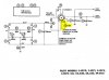
The 215 and 216 both use DC heaters, like the 210 (the Sams folder for both of them shows the heater winding at something weird like 38V, 0.6A, and that’s with the three additional 12AU7s). I didn’t look over the 550 power supply.

I was more curious about why the 215, 216, and 550 all changed that cap and resistor value in a mirror-imaged fashion from the apparent values in the P-10.

It’s also interesting that Pilot was so dedicated to cathode follower outputs. I skimmed over my collection of preamp schematics from Fisher, HH Scott, Dynaco, Fairchild, etc., the only ones I could find with a cathode follower buffer were the Fisher 400-CX and 400-CX-2, which used a 7247 in each channel for the final two stages, the low mu half being wired as a cathode follower. Most followed the traditional pattern of a 12AX7 final stage.

(I didn’t include the Knight KP-50, that thing wanders well off the beaten path - running several 12AT7s feeding into a 400mH choke in each channel. Odd duck. It will be interesting to see what it sounds like when I finally get around to it.)
 
In their era honestly the follower would be a lot less critical. Pretty unusual for a tube amp to have input impedance low enough to need it. Out of my own collection i think the lowest is 220k, and most things won't have trouble with that.

Makes them more useful now with solid state amps though.
 
Back
Top Bottom