• The move to the new server is done. There are some software and database maintenance updates in process. This has us passing the hat around to help out. We appreciate any donations. Seriously, even a dollar helps. The payment page may be found here - https://www.audiokarma.org/support.html

Pioneer 1280 Power supply issue

Leokarma

Well-Known Member
I've got an SX-1280 with power supply issue. I've checked all output voltages on power supply board and everything is OK except pins 16,17,18 where the voltage is +0.7VDC as against +13 VDC. All there pin get +13 VDC from collector of transistor 2SB682. Can someone confirm if transistor 2SB682 is toasted or something else ? See attached picture 1280.jpg
 
Register to hide this ad
many more voltages are needed to tell. all three on all three transistors, both sides of r15 to ground.

wild guess D13 is shorted, but the next question would be why, and what else was damaged and what else was destroyed.
 
agree, need more v readings and test those transitors, diodes.. you have a voltage doubler there, wild guess it is C18,19 issue.
 
There is no 20 VDC on emitter and Base. Its 0.2 VDC on base and O.7 VDC on emitter.

Voltage on D13 (emitter of Q7) is 0.2 VDC instead on 6 VDC.
 
Last edited:
Check fuse 2, (2 Amp's). The 13v supplies the tuner with juice. Both the AM and FM sections. A PA chip Might be toast. IC Q6 or Q7?
 
OK i'll check fuse but just to let you know when I turn ON the receiver it does turn ON and I hear the click sound after 2~3 sec.
 
There is no 20 VDC on emitter and Base. Its 0.2 VDC on base and O.7 VDC on emitter.

Voltage on D13 (emitter of Q7) is 0.2 VDC instead on 6 VDC.

Then check for AC voltage at pins 14 and 15. If the AC voltage is present then check R15, D11, D12, also check D13 as suggested earlier.
 
Then check for AC voltage at pins 14 and 15. If the AC voltage is present then check R15, D11, D12, also check D13 as suggested earlier.

On pin 14 its 9.5 VAC but on pin 15 its +12.5 VDC (no AC). Do you still want me to check R15, D11, D12 and D13 ?
 
check r15 power off ..should read 1 ohm .. if ok then measure ac volts from 14 to 15 ..power on of course ..
then for fun pull fuse 2 and measure voltage at pin 15
 
Last edited:
On pin 14 its 9.5 VAC but on pin 15 its +12.5 VDC (no AC). Do you still want me to check R15, D11, D12 and D13 ?

To check for AC measure "across" 14 and 15. Wire connections on pins 14 and 15 eventually lead to a separate transformer winding. So the voltage at that point has yet to rectified to DC. If the AC is present, then you need to check R15 as mentioned earlier. As Pete mentioned just power receiver down and check the resistance of R15. Its only 1 ohm so your meter is going to read nearly a dead short if its good. Also check the diodes while you're at it.
 
check r15 power off ..should read 1 ohm .. if ok then measure ac volts from 14 to 15 ..power on of course ..
then for fun pull fuse 2 and measure voltage at pin 15

R15 reads 1.6 Ohm.
AC Voltage across 14 and 15 (Black on 15 and Red on 14 or vice versa) is 9.5 VAC.
Fuse 2 pulled out I get +0.5 VDC on pin 15
 
To check for AC measure "across" 14 and 15. Wire connections on pins 14 and 15 eventually lead to a separate transformer winding. So the voltage at that point has yet to rectified to DC. If the AC is present, then you need to check R15 as mentioned earlier. As Pete mentioned just power receiver down and check the resistance of R15. Its only 1 ohm so your meter is going to read nearly a dead short if its good. Also check the diodes while you're at it.

Check Diodes - You want me to remove the diodes from PCB and check right ? Sorry for asking....not an expert.....
 
Check Diodes - You want me to remove the diodes from PCB and check right ? Sorry for asking....not an expert.....

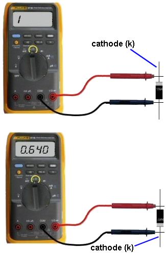
Power Off, check them in circuit using the diode test.


DiodeTesting.jpg
 
Here are the result of Diode test :-

D13 - Shows 0.374 in both the directions so its open.
D12 - Shows 0.575 in one direction and on other direction it shows volt rises slowly from 0 to 1 V and then shows "OL"
D11 - In both the directions it shows continuous rising voltage till 1 V and the shows "OL"
 
Here are the result of Diode test :-

D13 - Shows 0.374 in both the directions so its open.
D12 - Shows 0.575 in one direction and on other direction it shows volt rises slowly from 0 to 1 V and then shows "OL"
D11 - In both the directions it shows continuous rising voltage till 1 V and the shows "OL"

D12 looks Ok,
But D11 looks like its open and D13 looks to be bad. but since you're getting a reading in both directions, pull at least one leg from circuit to confirm its condition.
In many cases you can measure them in circuit. But if you get an abnormal reading sometimes it's the surrounding components throwing the reading off.
 
D12 looks Ok,
But D11 looks like its open and D13 looks to be bad. but since you're getting a reading in both directions, pull at least one leg from circuit to confirm its condition.
In many cases you can measure them in circuit. But if you get an abnormal reading sometimes it's the surrounding components throwing the reading off.

I pulled one leg of D13 and checked. D13 seems to be OK. It's showing 0.675 V in one direction and "OL" in the other.

I also pulled one leg of D11 and checked. It's showing 0.001 V in both the direction.
 
Back
Top Bottom