• The move to the new server is done. There are some software and database maintenance updates in process. This has us passing the hat around to help out. We appreciate any donations. Seriously, even a dollar helps. The payment page may be found here - https://www.audiokarma.org/support.html

Pioneer A-27 Power Supply Issue

Japetus

Nightshift
Dear AKers,

I sort of reposte this with new information from older thread, but this issue is not solved already.

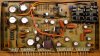
Picture shows circuitry of A-27 Power Supply AWR-176.
The issue showed up as A-27 getting too warm, warmer than already usual.
The cause is too high output voltages (Pin 8: +72.6 instead +65, Pin 6: -73.6 instead -66).
I took out the PCB to Lab and supplied +80V to Pin 21, and -80V to Pin 20, 0V to Pin 19.

After doing so, I took voltages all over the +80/-80 part of the board (red part).
Most suspicious values:
Q13 (2SC1649): Base 0V, Emitter 0V, Collector +76V

Measured Q9, Q10, Q11, Q12 and Q13 to be OK, also R26 and R28.

Found that D21 (MZ-081) is dead short.

Though not being an electrician, this seems to be enough reason for the issue.

What would be a suitable replacement for D21 at this position?
Are there follow-up damages likely for other components?

Best regards, Frank

A-27_Power_Supply_AWR-176_marked2.JPG
 
Register to hide this ad
This is a Mouser.com part number for an 8.1v zener diode: 771-NZX8V2B,133 for D21.
It is quite common for all the closely dc coupled components in that kind of circuit to kill or damage each other when one fails. I would replace Q13, Q9 and Q11 at the same time as D21, without powering up between part replacements.
 
You removed D21 and measured it as a short in both directions?
I can suggest to change the ecaps( polarized electrolytic capacitors) as well since you have it all apart. Match value, voltage, using 105C rated ecaps. As for changing Q13, Q9 and Q11, might not be necessary, but do the diode test on all of them.
 
You removed D21 and measured it as a short in both directions?
I can suggest to change the ecaps( polarized electrolytic capacitors) as well since you have it all apart. Match value, voltage, using 105C rated ecaps. As for changing Q13, Q9 and Q11, might not be necessary, but do the diode test on all of them.
Yes, I removed D21. I use a component tester (Peak DCA55, it automatically detects how a component is connected to it), and it showed 'short circuit'. Additionally resistance measures to be 1 Ohm in both directions. I am pretty sure it is kaput.
I did test all transistors I mentioned (Q9, Q10, Q11, Q12 and Q13) the same way, removed from board. All showed to be OK.

I would definetely follow your suggestion on electrolytics if did not already (restauration already about 2 years ago, you did help me a lot there, A-27 acquired eventually, about to be overhauled | Audiokarma Home Audio Stereo Discussion Forums)

@merlynski:
Thank you very much for your answer. I will check datasheet with mouser, maybe I'll find an assortment of suitable zeners.
 
You are welcome!
Testing transistors on a Peak DCA (or ohmmeter) will tell you if they are bad, but does not prove they are good, since it does not test under real world conditions. I have seen power supply regulator circuits come back to life by changing just one component, but have seen more that have a circle-of-failure where putting a new component in a circuit causes it to keep failing because the other connected components (that seemed to test good) fail under full load conditions. Buy extras and be prepared . . .
 
You are welcome!
Testing transistors on a Peak DCA (or ohmmeter) will tell you if they are bad, but does not prove they are good, since it does not test under real world conditions. I have seen power supply regulator circuits come back to life by changing just one component, but have seen more that have a circle-of-failure where putting a new component in a circuit causes it to keep failing because the other connected components (that seemed to test good) fail under full load conditions. Buy extras and be prepared . . .
I was afraid that might be possible, and I tend to follow your recommendation now.
So, for replacements, would you agree the following:
Q9: 2SC1649 -> KSC1845F ?
Q11: 2SD712 -> KSC2073TU or MJE15032G ?
Q13: 2SC1649 -> KSC1845F ?

And if I do so, would it be recommendable to also replace their symmetric counterparts, as
Q10: 2SA834 -> KSA992F ?
Q12: 2SB682 -> KSA940TU ?
Q14: 2SA834 -> KSA992F ?

Those (Q9 to Q14) I do have in stock, but if the replacements are not suitable, I would like to add others to the order list.
 
I would use a KSC2383 for Q9, it has a higher collector current rating than the KSC1845.
KSC1845 is a great choice for Q13, and KSC2073 is good for Q11.

The negative voltage regulator (Q10, Q12, Q14) are a 'voltage mirror' regulator tracking the positive side, they will not come up until the positive side is working, but I suggest to wait until the positive side is good before replacing those components, they may be fine.
For Q10 I would suggest a KSA1013 instead of the KSA992, for the same reasons as the Q9 suggestion.
 
That's great! That is what I'll do.
I do have couple of KSC2383Y and also KSA1013Y still in stock, so I could start replacing them (the positive side at first) tomorrow - but the zeners will have to be ordered.
Thank you very much!
OT: Someone who mentions Adm Grace Hopper in his signature, can't be wrong. Her 'nanosecond' is brilliant, as well as was all her way to explain and get a grasp on seemingly complicated matters.
 
You are welcome.
I had the same question about a nanosecond and calculated it myself.
You are the first to know who Admiral Hopper was and mention her. Thank You! :biggrin:
 
My pleasure!
Maybe I'm the first to mention, but surely not the first to know who she was.

Concerning the voltage mirror, am I correct on the following:
The unit got too warm, because the short circuit in D21 caused higher voltages at Pin 8 (the positive rail, measured +72.6V) and subsequently higher currents through Q9 and Q11 (at least).
It also caused higher voltages at Pin 6 (the negative rail, measured -73.6V), and therefore Q10 and Q12 also experienced higher currents than regularly scheduled.
Is that correct?

In addition, since these (regularly +65V and -66V) are supplying the power amp board, I hope nothing there is damaged, since it took a little (some days maybe) to recognize temperatures get too high.
At least it worked until I turned it off...

I almost can not wait to get the A-27 up again, since it clearly delivers the finest sound of all my equipment, especially when listening to my old (and new) vinyls.
Order at mouser is out, hope that does it...
 
The short of D21 is probably just a part of the failure of the positive regulator, the regulator failure (of Q13 going open) caused it to not drop enough voltage CE of Q11, it saturated and fed the full input voltage (pin 21, +80vdc) of the regulator to the output (pin 8, became +72 instead of +65vdc.) Since the negative supply mirrors the positive supply, its output voltage also increased. That put excess voltage across the circuits driving the outputs, causing it to overheat. Probably increased the bias current. That is a speculation on my part, but seems logical. There may be more damage to find, but it has to be 'one step at a time' until it is all repaired.

The voltage mirror works by monitoring the positive rail voltage with one end of the voltage divider of R29 and R30, to drive the negative voltage to (almost) match it. It is not perfectly balanced because the BE junction of Q14 has to be driven to about -0.6vdc to get it into its conduction range. So the negative rail has a slightly greater negative voltage then the positive rail's voltage. You can see that from the schematic you posted, the expected rail voltages are +65vdc (pin 8) and -66vdc (pin 6).
 
Last edited:
Thank you for your thorough explanation.
Maybe speculative, but totally plausible to me.
Now I have to wait for Mouser parts to arrive. I will replace D21, Q9, Q11, Q13 and VR2 in one step first, and check (Lab condition) if voltages are correct.
Then I will see for next steps.
 
Mouser arrived that day, so I replaced as announced:

D21 MZ-081 -> NZX8V2B,133
Q9 SC1649 -> SC2383
Q11 SC712 -> SC2073
Q13 SC1649 -> SC1845
VR2 ACP-064 -> 652-3362W-1-103 (single turn 10kOhm Bourns)

I remeasured voltages, but still got unreasonable values: Voltage at B and E of Q13 were now somewhere above 8V, but exactly equal.
Found that D15 is also dead short.
I do not know if this has been so right from the beginning, or maybe the initial failure, or even a new failure, so I rechecked D21, Q9, Q11 and Q13. They all still showed to be OK.

Since I feel to start loosing patience, I also directly replaced
D15 1S2437 -> 1N4148
Q10 SA834 -> SA1013
Q12 SB682 -> SA940
Q14 SA834 -> SA992
VR1 ACP-064 -> 652-3362W-1-103 (single turn 10kOhm Bourns)

Now voltages seem to fit, and I was also able to adjusted Pin 8 to 63V using VR2 (on purpose a little below 65V, final adjustments will be done in unit).
At the same time at Pin 6 it reads -64V.
Additionally I added some more and larger heatsinks (see pic). Since they are alive, they do not touch, have at least 2mm of distance.

Tomorrow I will give it a try, put the power supply back into the A-27 and start on DBT first.

PS_after3.JPG
 
Well, it is not done so far.

Volume to zero, no signal input, all switches to neutral.
Turned on on DBT, and as expected, after one second of bright lights, it dimmed down. But not as far as I had in memory, but this could be an error on mine.
With power amp assembly disconnected, it dimms down to almost be invisible.

I took voltages at Pins 8 and 6 (with power amp connected), they are about +53V and -53.5V.
Rotating VR2 does not change pin 8 voltage anymore.
I am not sure that this is due to DBT, but it does not seem to be as supposed.

But for now I refrain from starting without DBT until further checks of power amp assembly AWH-079.

Best regards,
Frank
 
What is the wattage of the bulb in your DBT? Once a unit passes the DBT test it is usually good to go to full mains, especially when working on power supply problems.
What is the AC voltage across pins 20 and 21?
What is the DCV on the collector of Q11?
If your voltage there is too low the regulator cannot come up into its proper regulation range, so adjusting VR2 will have no effect.
When you were bench testing the board you appeared to be feeding DC into pins 20 and 21 (from your posted schematic) instead of AC. That appears to work because the D7 -D10 bridge rectifier passes the DC current without a problem. If the board was working on the bench, and now does not work in the amp, the problem may be before pins 20 and 21. Or it may be the DBT bulb is too low a wattage . . .
 
What is the wattage of the bulb in your DBT? Once a unit passes the DBT test it is usually good to go to full mains, especially when working on power supply problems.
What is the AC voltage across pins 20 and 21?
What is the DCV on the collector of Q11?
If your voltage there is too low the regulator cannot come up into its proper regulation range, so adjusting VR2 will have no effect.
When you were bench testing the board you appeared to be feeding DC into pins 20 and 21 (from your posted schematic) instead of AC. That appears to work because the D7 -D10 bridge rectifier passes the DC current without a problem. If the board was working on the bench, and now does not work in the amp, the problem may be before pins 20 and 21. Or it may be the DBT bulb is too low a wattage . . .

-> I used two 60W in serial, so 120W total.
-> AC voltage was between 45 and 46V at both pins, measured with trueRMS meter - hope I have it correctly in mind, could not take measures now since it is apart again.
I did not note last values on Q11 at bench, but it was betwen +76 and +78V (DC).
I will take new measurements later and report, I did not measure in situ at collector of Q11.

Yes, you are perfectly correct regarding bench testing. I have a double lab power supply, each supplying 0 to 40V (max 3 Amps each). If I couple them in serial, I can feed 0 to 80V (or 0 to -80V), if using them separately, I can use a common ground and feed -40V and +40V at the same time. But I can not feed -80V and +80V simultaneously.
And yes, I fed it into the regular AC Inputs of pins 20 and 21. I hoped that rectifier diodes won't care...

But, this is surely not the same as feeding as the unit itself does, but I hope it is sufficient to identify damaged or not working components.

Would you agree on that? I am much less of an electrician than I would like to be, hopefully not too less than I need to be.

My next step would be to check all regular diodes (10 per channel, encircled red) of the power amplifier. I will take each one out and use the Peak DCA55 for it.

Would you suggest to replace them (1s2471 and 1s2473 with 1N4148) anyway, since having them out would not mean more work?

Best regards,
Frank

A-27_Power_Amp_AWH-079_circuit_marked_red.JPG
 
Two 60W bulbs in series will only pass 30W, and will really choke off the power supply. A single 60W bulb will allow a maximum of 60W IF the amp/transformer is a dead short across the power line. Then there is no power into the amp. Two 60W bulbs in parallel will allow 120W to pass.

Because the negative regulator is a voltage mirror of the positive supply it will never come up if the positive regulator is not working properly.

But, this is surely not the same as feeding as the unit itself does, but I hope it is sufficient to identify damaged or not working components.

Would you agree on that?

No, your testing premises are flawed. The power supply has a 'center tapped full wave bridge rectifier' as its first stage, and the common point is the center tap on the transformer secondary (to chassis ground) so the bridge must be fed with an AC source (to pins 20 and 21) to get the bridge rectifier to produce positive and negative DC outputs at the same time. If you could feed it, on the bench, with both +80vdc and -80vdc, with the common 'ground' connected to pin 19 you could bench test it that way. +/- 40vdc is insufficient to drive the regulators into their functional region.

Here is a block diagram of sorts of the circuit under question:

center-tap-bridge.png

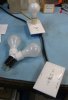
Here is my DBT, using one or two 60W bulbs, for 60W or 120W ballasts:

DSCF0847small-crop.jpg

The two bulbs in the Y are parallel, and get plugged in, replacing the single bulb. The Amp under test plugs into the open outlet next to the ballast bulb.

Get all the power supplies working correctly FIRST before moving on to the power amp section.
 
Last edited:
Thank you for taking the time and let me learn something here!

The DBT is supposed to have 120W. I will check the DBT, I built it about 11 yrs. ago, and it worked well with my previous restaurations (among others this A-27 two yrs ago, an SX-1080 10 yrs.ago) - I am sure I memorized it wrong, and it is actually 2x 60W in parallel - sorry for that.

Certainly I adhere to your suggestion, and try to get the supply fixed first.
This means I have to check the power supply in place (using the A-27 as supply) , since I cannot supply +/-80V AC otherwise.

Edit: If I was not clear enough, to be sure: I can only supply 0 to +40V and 0 to -40V DC simultaneously, or 0 to +80VDC or 0 to -80VDC at a time.

To do so (supply +/-80VAC simultaneously), and not impose possible further harm to the power amp, is it OK if I do not connect the power amp assembly only (connector with pins 6 to 11, see picture 5 posts up) and take measurements on the supply then, on DBT, having confirmed the DBT has two times 60W in parallel?

Best regards,
Frank
 
Last edited:
The DBT acts as a ballast, it limits current and reduces the voltage input to the amp, limiting the power dissipation in the amp to 'safer levels'. I use 60W initially as a greater level of protection. If it passes (bulb flashes bright, then dims) I try it on 120W. Once it passes that I go to full power UNTIL I make a significant change, then go back to power up on DBT, and do a retest cycle again. The Amp will not work properly until you can safely apply full power, power supplies will be low, music won't play properly.
If the power supply board is disconnected, you can somewhat determine what AC voltage the power supply expect by measuring AC volts from pin 6 to pin 7 on the Fuse Holder Ass'y, GWX-139. This measurement will give you the almost full secondary winding voltage*. Or you can clip one side of the meter to the chassis and measure one pin at a time, since the transformer has its center-tap connected to chassis ground. This will be the input voltage the rectifier/regulator sees. This is a very complex power supply, with multiple separate secondary windings from multiple transformers driving multiple rectifiers, feeding regulated and unregulated supplies. *
Adding to the complexity is the Surge Killer AWX-145, which limits a power surge coming in, just like the DBT does, until the +51vdc from power supply pin 12 on the AWR-176 causes the relay on the Surge Killer to pull in. Until the relay pulls in the power supplies will be low as well.

Edit: If I was not clear enough, to be sure: I can only supply 0 to +40V and 0 to -40V DC simultaneously, or 0 to +80VDC or 0 to -80VDC at a time.
Neither of those options will be of any use for bench testing the power supply board. Sufficient voltage must be supplied to both pins 20 and 21 at the same time to bring both regulators up at the same time

FYI, AC voltage is not designated with a '+/-' as its polarity switches every cycle, only DC has a + or - polarity to a chosen reference, in this case chassis ground.

This unit can be repaired, but it is going to take some work to get through all the physical. electrical, and logical paths to get the power supplies up. I would unplug / remove the power amp PCBs (AWH-079) until the supplies are all verified. That will protect the power amps. Then the Power Amps need verified / repaired, another complex task. I would also mark the location and remove each output transistor, and set them to the side. They will need tested, unless you just want to replace them. I don't know what to use for replacements (yet), but at least they are TO-3 packages, rather than an obsolete case design.
This will not be done quickly, but eventually, Alles wird in Ordnung sein.
 
The DBT acts as a ballast, it limits current and reduces the voltage input to the amp, limiting the power dissipation in the amp to 'safer levels'. I use 60W initially as a greater level of protection. If it passes (bulb flashes bright, then dims) I try it on 120W. Once it passes that I go to full power UNTIL I make a significant change, then go back to power up on DBT, and do a retest cycle again.

I checked my DBT, it is actually 2x 60W in parallel, so 120W as supposed to be.
Simply unscrewing one bulb reduces to 60W, that is what I will start with from now on. If 60W dimms down, then switch to 120W.

If the power supply board is disconnected, you can somewhat determine what AC voltage the power supply expect by measuring AC volts from pin 6 to pin 7 on the Fuse Holder Ass'y, GWX-139. This measurement will give you the almost full secondary winding voltage*. Or you can clip one side of the meter to the chassis and measure one pin at a time, since the transformer has its center-tap connected to chassis ground. This will be the input voltage the rectifier/regulator sees.

Here it goes (all connectors to power supply disconnected, wall socket power outlet delivers 230 Vrms, equal 325 Vpp or 162.5 V single sided amplitude):
DBT 60W, pin 7 to 6 fuse holder GWX-139 -> 112 Vrms equals 158.4 V single sided amp
DBT 60W, pin 7 fuse holder GWX-139 to chassis -> 50.6 Vrms equals 71.6 V single sided amp

DBT 120W, pin 7 to 6 fuse holder GWX-139 -> 121 Vrms equals 171.1 V single sided amp
DBT 120W, pin 7 fuse holder GWX-139 to chassis -> 54.5 Vrms equals 77.1 V single sided amp

no DBT, pin 7 to 6 fuse holder GWX-139 -> 123 Vrms equals 174 V single sided amp
no DBT, pin 7 fuse holder GWX-139 to chassis -> 55.6 Vrms equals 78.6 V single sided amp

This will not be done quickly, but eventually, Alles wird in Ordnung sein.
Thanks for keeping my hopes up.
My english is not as it should be, and I'm sure every now and then, there's a difference between what I write and what I think it means - unnoticed by me. Sorry for that.

Up to now, in the last 10 yrs, I mostly only replaced components (electrolytes, transistors and others), without having grave issues before.
This case seems to be a bit more asking now.

Best regards and a nice sunday,
Frank
 
Back
Top Bottom