• The move to the new server is done. There are some software and database maintenance updates in process. This has us passing the hat around to help out. We appreciate any donations. Seriously, even a dollar helps. The payment page may be found here - https://www.audiokarma.org/support.html

Pioneer A9 repair in 2022 appreciatte any advise help

Status
Not open for further replies.

Carguy1394

Active Member
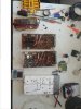
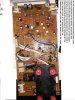
Hello everyone in this forum. I will be grateful for any advice and help that someone gives me because I have not repaired any amplifier so far. This is another renovation of Pioneer A9. It differs from all the repairs described so far in that most of the transistors recommended here for substitution are no longer available. The other feature is that it is a repair of 3 A9 amplifiers with different degrees of damage. I bought one from eBay - amp number 1. It played but there were problems with its potentiom20220126_105212.jpg 20220126_105901.jpg eter

and switches and the bias was not set obviously because it was absolutely cold both at idle and when playing for a long time. I tried to adjust the bias but I must have done something wrong because the left channel exploded and a piece of 2SA1076 transistor crashed into my forehead and the 150 ohm resistance between the drivers burned with a flame in front of my eyes. The transistors on the left channel were burned out, the drivers, the double ceramic resistor, the 150 ohm resistor 05V, the A899B preamplifier on the amplifier board and the resistors. It turned out that the amplifier had been repaired many times. Just then another came out in Ebay with a defect in the left canal. I bought it right away because I thought it was easy damage or I would take parts of it - this is amplifier number 2. It turned out that it has different transistors 2SA1301 & 2SC3280 the left channel and the left channel curved over 2 watts of gain, and it was cold. I thought it was bias, but this time I put on my glasses before adjusting. I started to adjust very carefully with Fluck115 and a ceramic screwdriver. At that time, I was blown away by the heat of Pioneer A9 and the smell of aluminum. I immediately panicked and turned off the amplifier. And then I saw that the right, working channel had melted the transistors. I never imagined that bias could have such a significance for Pioneer A9. Then I bought transistors from ebay 2SA1076 and 2SC2526. I replaced the other burned parts again from ebay and proceeded again very carefully to adjust the bias This time I don't know where my mistake was, but both channels smoked from overheating. I was completely desperate that I could not repair these two amplifiers and bought a third Pioneer A9 from ebay amplifier number 3. It looks better preserved, although it has been repaired. I don't know if the power transistors are original. Here I will post photos of this investigation. I decided to check the bias just in case before there was any trouble. But this time, without turning anything, I touch the radiators at idle with my hand. Slightly warm, that's fine. I immediately measured the voltage in both ends of the resistor R1 and R2 of 150 ohms 0.5V which is on the driver boards on the right channel at one end is +0, ...and at the other is -0 ... 1volt difference In this channel is OK. But on the left it is the same at both ends +0 .... 0 volt difference Which means that no current flows through the R1 of GWX 593 to unclog the drivers. The other two amplifiers that exploded in my hands had the same problem. What can this be - bias? Drivers, pre-drivers. Anyway. I decided to throw away the other two amps and keep the last one. But then I decided to fix all three, starting with the broken ones to gain experience.
 
Register to hide this ad
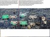
I hid the still NOT exploded amplifier from myself in storage 6 miles far from me. I start with the two destroyed by the explosion in the fine tuning of the bias. The final transistors are in pieces and I must also determine whether they are genuine or counterfeit Chinese garbage. So I broke them to see the size of the crystal and the difference between the different types of transistors that exploded in these amplifiers. I also inspect the GWH-148 POWER AMP ASY, de solder all the transistors and measured and recorded them on each hFE. Then with a magnifying glass increase X12 I inspected all the components of the board in strong sunlight. The burned-out resistors are immediately recognizable. It is not necessary to de solder and measure this is a waste of time and will damage the tracks on these old and repeatedly repaired boards. I measured the diodes on the board and they were fine there was no short. components Q29 Q30 Q31 Q32 Q33 Q32 Q34 total for both boards and 100 ohm resistances to them R65 R66. The power supply has replaced parts of the GWR-141 board. There were burns transistors with radiators, someone had replaced the field-effect transistors 2СК34 and something else and also the zener diode KZL-140 was replaced with two components consisting of a diode and another diode or diode and zener I could not understand. I decided to stick strictly to the original condition and I bought 2SK134 used . For KZL-140 according to the size of the case and also according to the place where true KZL-140 the current should be between 0.006A and 0.01A according to my calculations KZL-140 is 14V 1/2A. So I will may be try to simulate the electrical situation on the GWR141 and to bench tested the KZL-141. But for me is sure that is not possible to be 1W because for 1.3 W is the next size of case . So I will replace KZL-140 with 512-1N5244B according to recommendation of markthefixer and will post the result and also the result from the equivalent bench test.Know I am posting picture of two different type transistors. You can tell your opinion are they genuine.
 
I have to stress.
You have to check every component for serviceability.
Maybe the ceramic's not so much. On second thought, better check them.
When these amps let go, all Hell breaks loose.
Use known good suppliers for any transistors.

The deal on these? Even if the silicon components test (Mainly in the driver and final stages) they are considered "survivors" and will fail shortly.
Maybe you can make one good one from the three?
 
I have to stress.
You have to check every component for serviceability.
Maybe the ceramic's not so much. On second thought, better check them.
When these amps let go, all Hell breaks loose.
Use known good suppliers for any transistors.

The deal on these? Even if the silicon components test (Mainly in the driver and final stages) they are considered "survivors" and will fail shortly.
Maybe you can make one good one from the three?
Nothing of the subs listed here from markthefixer is not available know from mouser, Newark etc.. On the final stages there are not suvivors after the precisely adj of the bios. I am doing exactly this- check all the components. but the drivers and pre drivers and the subs for 2SA1076 AND 2SC2526 ARE THE PROBLEM
 
once you got shrapnel flying, nothing is considered good until proven so. at those power levels, semiconductors can no longer be trusted not to fail after the slightest provocation.
semiconductors is not just transistors, it include DIODES.

i too experienced NSA shrapnel long ago...

parts (usually) can be sourced through AK'er eastwood.

you may not get exact size and shape replacements, but rather modern cases that will work well enough.

You sir have done the equivalent of jumping into the cockpit of a 747 in flight and declared yourself ready to learn.

just where exactly ARE you?
 
once you got shrapnel flying, nothing is considered good until proven so. at those power levels, semiconductors can no longer be trusted not to fail after the slightest provocation.
semiconductors is not just transistors, it include DIODES.

i too experienced NSA shrapnel long ago...

parts (usually) can be sourced through AK'er eastwood.

you may not get exact size and shape replacements, but rather modern cases that will work well enough.

You sir have done the equivalent of jumping into the cockpit of a 747 in flight and declared yourself ready to learn.

just where exactly ARE you?

Thank you for your time and attention to my problem. I had no desire to fix any amplifiers, I just wanted to listen and enjoy the A9, but as I described in detail above I was not lucky enough to come across something in good condition. I even wore the first amplifier in Chicago masters Stereo Rehab . When they saw him, they immediately said that they couldn't fix it, and they offered me some Denon for free, just for what I had spent there. I refused, thanked them, took my blown A9 and realized that I should either throw it in the container or try to fix it myself. Then I came across Audiokarma and read everything about the repair of the A9 that is written here and I wrote down all your advice and substitutions in parts. The bad thing is that almost all of these parts are no longer available. My repair strategy is to inspect all the boards, remove the transistors and check them, check the resistors with a magnifying glass in the sunlight to see if their paint has burned out, measure the diodes on the board in both directions and if there is a short I remove them and I check them again, I also measure the zeners on the board for short and one-way conductivity. Electrolytic capacitors are measured for ESR and not electrolytic capacitors I measured for voltage and micro amps leakage , the field-effect transistors as shown on YouTube. Unfortunately, I do not understand electronic circuits and I do not know whether only the replacement of defective parts with fit ones will solve the problem. It is also obviously not clear how to adjust the bias of this amplifier because it is not normal for every amplifier that is touched to explode. I will be happy if you take the time for advice and guidance because really few people know how the NSA works. Especially this High frequency servo bias that blows up the A9


My location is Mount Prospect, IL, 60056.
 
I'm optimistic.
It's going to be an uphill battle but an entertaining one.
There was a thread a few years back on a SX-3800 - 3900 NSA amp? where the OP sub'ed modern Fairchild transistors in.
Mark, Meryln and Rick advised. See if you can find that one for reference.
 
I'm optimistic.
It's going to be an uphill battle but an entertaining one.
There was a thread a few years back on a SX-3800 - 3900 NSA amp? where the OP sub'ed modern Fairchild transistors in.
Mark, Meryln and Rick advised. See if you can find that one for reference.
Thank you for the info and support sir ! I will take look for this link also
 
"Unfortunately, I do not understand electronic circuits and I do not know whether only the replacement of defective parts with fit ones will solve the problem"

A destroyed part is almost always an innocent victim, with the reason and problem of that destruction being external to that part.

Thus replacing a destroyed part without correcting the causative problem will only get at least another destroyed part, with a strong possibility that before the replacement part is destroyed, other additional parts will be destroyed.

in other words: "Makes it Worse".
 
desoldered plate amp.jpg
"Unfortunately, I do not understand electronic circuits and I do not know whether only the replacement of defective parts with fit ones will solve the problem"

A destroyed part is almost always an innocent victim, with the reason and problem of that destruction being external to that part.

Thus replacing a destroyed part without correcting the causative problem will only get at least another destroyed part, with a strong possibility that before the replacement part is destroyed, other additional parts will be destroyed.

in other words: "Makes it Worse".

I absolutely agree with that! I have such experience in my field of work in the automotive. Seven times they repair the transmission and it burns. The customer has taken power for the 2000W amplifier from the TCM power supply circuit or from the pressure regulator circuit. My first question is: Is there an amplifier installed?

The mechanic answers - yes, but we have no problem with the music but with the transmission.
If the cause of the damage or chain reaction of damage is not found, or there may be several reasons why each of them causes a chain of damage and they mutually influence each other, then the repair is unsuccessful. This requires a diagnosis. And the correct diagnosis requires the right person who knows how each part of the system and the whole system works and who has experience. Therefore, the advice of the right one man are the most valuable thing without which the amplifier is just a brick in which parts ,time , money and nerves are poured. This is what makes me feel insecure when repairing something that I do not know how it works or how to diagnose it. It is also clear to me that if the amplifier works, additional measurements, adjustments and also replacement of some parts will have to be made. That's what I'm thinking to solder in the points where the voltages of the board are measured wires with inscriptions at which point it goes and how many volts there should be on the wire. This would make it easier for me because the board is inaccessible after mounting to measure the voltage. Currently, both GWH148 boards have tested and soldered transistors. Tested diodes, tested zeners, tested resistances. Capacitors are tested for now only briefly. Some of the orange electrolytic capacitors are removed C28, C29 I am making list of defective parts.
Do you have some better idea what to do?
 
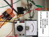
ABCD.jpg cap leak data.jpg I am confused should i change this capacitors. They looks quality caps ,additional are factory sealed with epoxy and they meet the specs fr the new one . Also they are long lasting. For the new one they give 2000 hours . I already ordered replacement for the orange ones .They are chip but I don't know how good they are comparing to this. I know that every body just replace them.They aging . they changed tg delta raising ESR and capacity , drying the electrolyte.. On my old Alpage Al 300 and Fillips N5781 all the capacitors are original from the factory and this decks meet the factory specs. Over there is also bias frequency 105 kHz
In my Nak ZX7 from the orange capacitors all was bad but this was non electrolytic caps.So will compare the new with the old by all parameters before to replace them.Also I apologies that the picture is tilt . In my computer is normal. I tray everything eater to give advance -90degre before upload but the result View attachment 2466358 is the same all the time. Sorry.
 
I can recommend some rather technical reading, from Pioneer.
It is called the tuning fork series, and was intended to get remote technicians more in tune with Pioneer's thinking.
It was a wide ranging series of bulletins issued periodically.

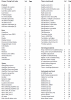
Here is an index that was done of them - it is the overview of the entire series.
https://audiokarma.org/forums/index...fork-service-guide.249745/page-4#post-6987860

https://audiokarma.org/forums/index.php?threads/pioneer-tuning-fork-service-guide.249745/

I suspect you should do an overview of the entire series, found in post #66, then decide upon an order in which to read them.
<a href="https://audiokarma.org/forums/index...fork-service-guide.249745/page-4#post-5831797">Pioneer Tuning Fork Service Guide</a>


alternate source:
https://www.hifiengine.com/manual_library/pioneer/tuning-fork.shtml

Edit HERE'S the index:
upload_2022-1-27_23-48-33.png
 
Last edited:
I can recommend some rather technical reading, from Pioneer.
It is called the tuning fork series, and was intended to get remote technicians more in tune with Pioneer's thinking.
It was a wide ranging series of bulletins issued periodically.

Here is an index that was done of them - it is the overview of the entire series.
https://audiokarma.org/forums/index...fork-service-guide.249745/page-4#post-6987860

https://audiokarma.org/forums/index.php?threads/pioneer-tuning-fork-service-guide.249745/

I suspect you should do an overview of the entire series, found in post #66, then decide upon an order in which to read them.
<a href="https://audiokarma.org/forums/index...fork-service-guide.249745/page-4#post-5831797">Pioneer Tuning Fork Service Guide</a>


alternate source:
https://www.hifiengine.com/manual_library/pioneer/tuning-fork.shtml

Edit HERE'S the index:
View attachment 2466377
This is very interesting and believe valuable info ! Thank you , I will definitely go true this info . Right know I am reading "High power audio amplifier construction manual 50 to 500 watts for audio perfectionist " and " Mastering Solid State amplifiers" Also looking in this forum and you tube. I will not intend to go too far into amplifiers education and after I fix my amps I probably will lose the interest of electronic repair of amps,because my business is automotive. But for know this is very interesting for me waiting the winter to finish
 
Here I have to mention something that I remembered the amp that worked well before it exploded from the bias setting. On this amplifier, I had removed the potentiometer to clean it because it was crackling. After disassembling it, I cleaned with Deoxit F5 and lubricated it, I decided to replace the electrolytic capacitors C1 up to C4 on the volume control board with non-electrolytic polyesters or polypropylene. I thought then that an audible signal was passing through them, which is nonsense
11.0pt">.I now remember , that the potentiometer regulates the feedback. I must say that there was a big one improvement in high frequencies - transparent long incessant detailing cymbals. He just played great. Here I see in the block diagram that the bias servo control passes from the end transistors and goes to the volume control board. My question is this: Is it possible that the replacement of the electrolytic capacitors C1-C4 with non-electrolytic ones affected the bias so that the final stage exploded which did not have a bias set and de facto worked in class B? In other words, is it possible that the lack of bias reduces the feedback function that protects the amplifier from self-excitation and it is self-excited with some high frequency that is amplified to infinity and this blew up the transistors. After the explosion the radiators were cold says it's not about overheating. In this regard, I see that an operational amplifier is also involved in this feedback. Is it possible that it has burned out and how can I check it or is it good to replace it if it is available anywhere at all?
And do I have to put the electrolytic capacitors there again? Thank you for the answers in advance!
 
Is there anybody who knows haw to disconnect the flat cable for the switch on the equalizer board
AWF 052 ?
 
Last edited:
I can recommend some rather technical reading, from Pioneer.
It is called the tuning fork series, and was intended to get remote technicians more in tune with Pioneer's thinking.
It was a wide ranging series of bulletins issued periodically.

Here is an index that was done of them - it is the overview of the entire series.
https://audiokarma.org/forums/index...fork-service-guide.249745/page-4#post-6987860

https://audiokarma.org/forums/index.php?threads/pioneer-tuning-fork-service-guide.249745/

I suspect you should do an overview of the entire series, found in post #66, then decide upon an order in which to read them.
<a href="https://audiokarma.org/forums/index...fork-service-guide.249745/page-4#post-5831797">Pioneer Tuning Fork Service Guide</a>


alternate source:
https://www.hifiengine.com/manual_library/pioneer/tuning-fork.shtml

Edit HERE'S the index:
View attachment 2466377
Very valuable info markthefixer! I download , I think everything or at lest over 90% of the things.I just did mot found the troubleshooting of power amplifiers.But there is priceless info for the vintage caps, resistors , transistors diodes , vintage coding etc. Most of the basic electronic I already learned into the university but there is a lot of practical info and data. Thank you Sir one more time for the valuable info!
 
I don't trust them. but I do go through silicon and I like to have things on hand - especially right now when supplies are a bit erratic throughout the world.

Irregardless of trust though, this is why we replace transistors with modern silicon with equivalent characteristics. Its far cheaper, more reliable and as well as that, modern silicon in some instances is just simply better, quieter etc than what was around in the 1900's.
What available subs from the modern new and better than 1900y you recommend for replacement of 2SA1076 and 2SC2526. I am repairing A9 and most of the subs recommend in AK in previous repairing of this amp are not available from the trusted vendors.
 
I have rechecked all transistors today and none are dead even the original drivers as was advised to keep by Mark the fixer I have also checked the final output transistors and they also checkout so it's happening under load as said. I'm not one for giving up so i will keep persevering I would say to plug the board in with no finals connected or one set of finals connected and see if it comes out of protection but if I leave all finals out the only things that will be connected are protection and the main filter caps. Also is there a possibility that the old driver transistors are not adequate enough to drive the new upgraded transistors in the board and it’s causing the -39v DC balance? Also what would be a suitable upgrade for the driver transistors thanks
Car mechanics switched the places of the suspicious parts and good known parts and looking if the problem change the place
 
Status
Not open for further replies.
Back
Top Bottom