• The move to the new server is done. There are some software and database maintenance updates in process. This has us passing the hat around to help out. We appreciate any donations. Seriously, even a dollar helps. The payment page may be found here - https://www.audiokarma.org/support.html

Pioneer A9 repair in 2022 appreciatte any advise help

Status
Not open for further replies.
I have to stress.
You have to check every component for serviceability.
Maybe the ceramic's not so much. On second thought, better check them.
When these amps let go, all Hell breaks loose.
Use known good suppliers for any transistors.

The deal on these? Even if the silicon components test (Mainly in the driver and final stages) they are considered "survivors" and will fail shortly.
Maybe you can make one good one from the three?
By this explosions there are not survives. I don't play games when adjusting amplifiers.Everything is burned to the ground. Let see what and from where to order it.
 
you need to remove the transistors and check for faulty ones,
thats the on load\off load voltages

although i always say its a good idea to realize ones limitations
I did it a couple times. Tested with a TC1 multi tester and also with a Fluke. Looks that they are ok. On the both sides of R1 should be -0.6 V and +0.6 V . This is connected with a bias may be
 
Hi guys Do you think the A9 is downgraded by having 15,000 uF capacitors installed. I read that if you put 20,000 or 22,000uF it will work better and have a better sound? And it is not very clear to me why these capacitors have 5 pins and only 2 of them are connected to the circuit? Can they be replaced with 2-pin capacitors? Did any body tray this?
 
i wouldnt bother about the capacitors until its working, 3 of the pins are for stability,

yes the bias cct from the preceding stage

Let me ask one more time before it explodes again. I see that they all work with DBT 100V. Then if something in the bias is wrong and the voltage it sends to unlock the driver is higher than 0.6V for example 2V and starts to gain and if the negative feedback does not work and does not reduce the gain then it can lead to damage of the final transistors. So my question is:

In such a situation, can the DBT connected to the power cable prevent damage to the transistors? Isn't it necessary to place two light bulbs between the large capacitors of the + and - terminals, which limit the current to the power transistors to 3A for example? Because if there is 100W DBT on the power cable the capacitors are charged with 50V and in case of possible unresolved damage in the bias I do not see how this DBT will save the final transistors. Please correct me if I'm wrong ..
 
when the o\p transistors take too much current the lamp in series with the supply limits the current to hopefully a safe level, if there are lamps where you mention then the voltages might not be equal and cause the circuit to misbehave
Yes. The lamp connected to the power cord limits the current exponentially if it becomes short at the starting torque before the large capacitors are charged. Yes that is right. But what happens if the amplifier turns on and after 1 minute there is a breakdown of some element of the bias and apply voltage to amplify the drivers and the transistors. In this case, the lamp at the power input does not play because there is accumulated energy well after the power supply next to the final stage. Then the big capacitors will discharge in a flash through the final transistors, which happened once and I have a scar on my forehead from shrapnel from 2SA1076. Could the imbalance of the system from the inclusion of 2 lamps on + and - on the large capacitors cause significant damage and which of the two possibility’s are more dangerous?
 
Yes. The lamp connected to the power cord limits the current exponentially if it becomes short at the starting torque before the large capacitors are charged. Yes that is right. But what happens if the amplifier turns on and after 1 minute there is a breakdown of some element of the bias and apply voltage to amplify the drivers and the transistors. In this case, the lamp at the power input does not play because there is accumulated energy well after the power supply next to the final stage. Then the big capacitors will discharge in a flash through the final transistors, which happened once and I have a scar on my forehead from shrapnel from 2SA1076. Could the imbalance of the system from the inclusion of 2 lamps on + and - on the large capacitors cause significant damage and which of the two possibility’s are more dangerous?
Ok I made the experiment . The two lamps DBT between big cap and the o/p transistors activating the protection mode on A9. So this is not an option. So the lamp for DBT on the power cord is the only easy option . Let see how it will work when I receive the repaired plates.
 
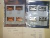
The Sanken transistors 2SA1216 and 2SC2922 h20220222_180342.jpg 20220222_180504.jpg ave just arrived, which are one of the few available substitutes for 2SA1076 and 2SC2526. Purchased from a distributor recommended by markthefixer. Ampslab.com. The first thing I measured was hFE and I wrote it on each transistor with a marker on the back. To my knowledge, for these transistors to work as a final stage, they must have the same gain or the same hFE to be complementary pairs. If a transistor has a higher xFE, it will absorb most of the pulse, load more, and distort the sine wave. So with a different hFE when working in parallel SEPP is not a good picture at all. Here I publish their photo. One of the transistors has hFE 222, which is above the maximum allowable for its class - for class D they give up to 180. I have a few questions "Do you think that these transistors are appropriate to mount on the A9 Pioneer? Do you think that they will work well and if I set the bias according to the specification for the original Fujitsu transistors, it will be good for these transistors as well? Do you think there is another place where I can order transistors and send me complementary pairs that have a mica? Do you think these transistors can be fake ?


https://www.ampslab.com/Freewares/2sc2922.pdf


https://www.ampslab.com/Freewares/2sa1216.pdf
 
I'm not an engineer, just a hobbyist. But this is my understanding. Someone with more knowledge will come along and explain it better..
I don't think those are counterfeit transistors. I don't think hFE means much on the final output transistors. The finals are just to handle current. The amp uses feedback to control the waveform coming out of these transistors. The transistors that must be matched are the differential pair. Complementary transistors, PNP vs. NPN, (almost) never have the same gain.Look at the data sheets for the originals. I'll bet they do not have the same gain for NPN vs PNP. I don't have time to look now. Good luck with your repair!

 
I'm not an engineer, just a hobbyist. But this is my understanding. Someone with more knowledge will come along and explain it better..
I don't think those are counterfeit transistors. I don't think hFE means much on the final output transistors. The finals are just to handle current. The amp uses feedback to control the waveform coming out of these transistors. The transistors that must be matched are the differential pair. Complementary transistors, PNP vs. NPN, (almost) never have the same gain.Look at the data sheets for the originals. I'll bet they do not have the same gain for NPN vs PNP. I don't have time to look now. Good luck with your repair!
Thank you for your response sir!
 
Although I have been repeatedly told in this forum that the final transistors do not matter what the hFE is, I am posting here the reason why I continue to ask this question. Let me remind you that this is a Pioneer A9 NSA, I hope to get a technically sound opinion from an electronic specialist why on page 28/33 of the service description it is explicitly mentioned that the final transistors must have the same hFE, which is consistent with my logic.

EN" lang="EN">There is a contradiction between the repair catalog of the Pioneer and the explanations in the AK. Could this be a mistake in the catalog or have the Pioneer engineers overdone it unnecessarily and it is really not necessary to attach such importance to this problem and even with a different hFE A9 will work from 5Hz to 200 kHz +0, -0.3dB and will keep all the other technical specks according to the service manual?
hFE.jpg
 
They are working in pairs, a great difference between each of the pair elements would result in unequal load sharing, which would result in reduced capacity.
 
They are working in pairs, a great difference between each of the pair elements would result in unequal load sharing, which would result in reduced capacity.
Sir, for a specialist like you, this is only a small part of the answer.
It will not only lead to reduced capacity. On quality music it will irritate me with distortions in the fine sounds . By forcing it to play at 100 watts it will overheat the transistor which has hFE 222 and works in parallel SEPP with the transistor with hFE 170, and the other half period will still be uneven load on one transistor with hFE70 and one with hFE45, which may not explode. I don't know how these gain curves will change at a voltage of 60V and higher amperage, but this transistor with hFE 222 which exceeds the maximum for class Y(180) by 40, will probably explode. Even if it doesn't explode, there will be intermodulation distortions unpleasant to listen to. This is provided that in some way this amplifier allowed him to tune the bias with these transistors with different amplification. (NSA!) They didn't even have the option to order from one class of amplified and they sent me class G and class Y. The bad thing about this ampslab is that there is no return option and you have to write emails which is not known if there will be a result. What seems to me to be happening is that high-quality analog parts are no longer produced and obsolete discarded parts from good manufacturers or straight scrap from ali are sold. Anyway if anyone knows a site where I can still buy quality substitutes I appreciate a lot.
 
Maybe they mean the letter grade marking and not actually matched???
There is so many opinions and no single prove with experiment. If is not possible to return this s-t I will post a result and measurements . Also if it start working wit this transistors
 
Sir, for a specialist like you, this is only a small part of the answer.

I certainly won't make this mistake again.

You need to realize that the Hfe varies greatly with the collector to emitter current in each device. NO way there is Hfe 222 at high load currents.
You need to know what currents your tester is using to get results.

From my perspective you are picking nits while having only a partial understanding of the underlying engineering, mathematics and realities of the subject.

Even using the data sheet graphs would have revealed that Hfe has current dependent curves. If not of that exact power transistor, then one from another contemporary power transistor.
 
Last edited:
I certainly won't make this mistake again.

You need to realize that the Hfe varies greatly with the collector to emitter current in each device. NO way there is Hfe 222 at high load currents.
You need to know what currents your tester is using to get results.

From my perspective you are picking nits while having only a partial understanding of the underlying engineering, mathematics and realities of the subject.

Even using the data sheet graphs would have revealed that Hfe has current dependent curves. If not of that exact power transistor, then one from another contemporary power transistor.


What kind of mistake are you talking about?
The current of the device at the time of testing is 5V, 0.007A ..
It can be seen from the graphs that hFE is function of Ic Vce ,T, f and letter of the class of amplification , which is very clear.
I do not know on the basis of what you made your conclusions that I understand partly from graphics, mathematics and engineering as I have a Master's degree in mechanical and electrical engineering. But this is just your opinion.
I have not dealt with the repair of amplifiers and that is why I have been in this forum for some time. Just out of interest and nostalgia.
Regarding hFE - I read 5 more forums in AK where people ask each other and there is no final opinion on the issue. Your answer also does not affect the question of whether all end transistors should have the same hFE.
Well, of course they have to - it says in the service description. I ask this question to see how accurately people repair their amplifiers. Obviously my requirements are higher and it's not just the amplifier to play. That is all. I'm done with this question. Who is hesitant whether or not to read the service description - it says so.
 
Maybe the service information is wrong. The question becomes do you want an amp that works or one that gets scrapped because the parts are no longer available? I'm not real familiar with this amp. Does it have multiple transistors for each channel? IE 2 PNP & 2 NPNs for each channel. That would make since to match those but I believe the emitter resistors make that unnecessary too.
 
Last edited:
Status
Not open for further replies.
Back
Top Bottom