• The move to the new server is done. There are some software and database maintenance updates in process. This has us passing the hat around to help out. We appreciate any donations. Seriously, even a dollar helps. The payment page may be found here - https://www.audiokarma.org/support.html

Pioneer CT-F900 repair help

Without an oscilloscope, we may be very handicapped. But let's see what a multi-meter reveals.

Relevant symptoms and indications:
  • Your transport is dropping to "Stop," immediately after entering rewind, indicated by dropping the brake.
  • Circuitry driving the transport components (brakes, reel motor, etc.) are functional, as indicated by play and FForward mode.
  • "Stop" is responded to at all times, and FForward function, so the deck cannot be hung at "Stop"
Rewind has a signal to trigger stop, or stop & play, as commanded from the display/control processor. This signal is only responded to during rewind. This leads me to suspect circuitry related to memory stop/play.

Do the following, and report back:
  1. Power on the deck, install a cassette, and select the "Off" button on the Memory - Repeat area of the display control.
  2. Set the meter to read at least 20v DC, and make sure that the black lead is plugged into the minus meter input, and the red lead is plugged into the plus meter input.
  3. Clip the negative meter lead (black) to the chassis somewhere.
  4. The Control Assembly is the board behind the transport.
  5. Clip the positive meter lead to connection 11 on the Control Assembly (connection post, not pin in a connector). There should be a wire tied to this connection post.
  6. Report the voltage seen by the meter.
  7. Watch the meter and try to put the deck into rewind (there should be some tape available to rewind). Report any changes to the meter reading that you see as the machine enters and drops out of rewind mode.
Enjoy,
Rich P
 
Last edited:
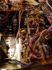
Ok so I have includes a photo of the pin i was measuring it is the purple one. So when powered on the pin is seeing 5.05 volts. When I press down the reverse button for less then half a second pin 11 shows 3.5. When i hold down the reverse button the voltage drops down to 1.59 volts. When in fast foward pin 11 reads 4.98 volts along with while it's in play. All these measurements where done with memory set to off as you said. Also another observation i made is that after I turn the machine off it takes 4 seconds for the voltage on pin 11 to start to drop, i figure it's a capacitor.
 

Attachments

  • 20160929_212854.jpg
    20160929_212854.jpg
    79.9 KB · Views: 28
  • 1475200473221-1683660826.jpg
    1475200473221-1683660826.jpg
    137.4 KB · Views: 25
Ok so when powered up the multimeter is reading 5.07 volts steady on pin 11 which is the one with the purple wire( i included a photo in case it was the wrong pin though I dont believe so). When I trigger the reverse action and press the button for half a second or so the meter reads about 3.5v sometimes dropping down to 3v but when I hold down the reverse button i get a min voltage of 1.59v. When i press fast forward It reads a steady 4.99v, play reads 5v.
 
Your measurement does not make sense. I can't tell from your picture which point you are measuring. It is a pin that is sticking up out of the board, with a wire on it, number 11. It is not a wire in a connector. It should be in the right rear area of the board, as you look from the front. The pin next closer to you is pin 9. You need to measure pin 11. Then make the same measurements on both sides of the resistor that starts in between pins 9 and 11 and goes right to left from there. Pin 11 is one side of the resistor, and the other side, closest to the big IC chip, is pin 11 of the chip. I need comparative readings from both sides of the resistor.

Be careful! If you make a short circuit during measurement, you will have a paperweight, instead of a tape deck.

Enjoy,
Rich P

 
These 900s have a common problem. There is a connector on the board behind the transport, big white connector with all the wires that go up to the transport. Two things happen - first, the pins on the board have cold solder joints. I've repaired cold solder joints on two 900s and an 850, so this is a common issue. The other is that the pins inside the connector corrode -- often so badly that they disintegrate. Poke in there with a bent paper click, and make sure that each pin in the connector is intact. You should feel resistance when you insert the paper clip into the connector. If it goes in easily, that pin has disintegrated. You'll need a new connector. You can also fix it by soldering the wires directly to the pins on the board, but it's a better idea to replace the connector with a new part.

Charles.
 
Back
Top Bottom