• The move to the new server is done. There are some software and database maintenance updates in process. This has us passing the hat around to help out. We appreciate any donations. Seriously, even a dollar helps. The payment page may be found here - https://www.audiokarma.org/support.html

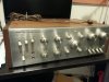
Pioneer QM-800A quad amp restoration

Aaron99

Active Member
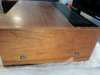
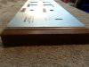
I recently acquired a Pioneer QM-800A and QC-800A as a secondary deal when purchasing a Marantz last week. The previous owner was was de-cluttering and tired of seeing it sitting on his shelf unused in his warehouse. The preamp QC-800A looked complete, and the QM-800A amp was missing 3 knobs. He said he can't remember when he bought it new, probably early to mid 70s. He said that the last time he used it was 20 or 25 years ago. I asked him if he knew any of the specs, and he said it was loud and rocked many parties in the 70s and early 80's. We negotiated a price and I took it home untested.

DBT
I plugged it into a DBT and it passed. A few seconds later I heard the relay click. The lights on the front panel were dead as expected.

Connecting
So I powered the amp off and get my sacrificial speakers. Looking closely on the back... WTF are those plugs? grumble grumble. So I carefully slide the speaker wires into the slots and get a pair of speakers hooked up.
OK next step. I get my mp3 player with the RCA out to plug into a Left and Right input.... WTF, the RCA ports are too close together for the width of the plugs... OK, so I will test them one at a time.

Testing
So I turned on music and was able to get music/sound out of 3 of the 4 channels. Channel 2 had loud buzzing.
I could adjust the Meter Level knob to see all 4 of the VU meters work. The meter for the channel 2 pegged when testing due to the buzzing on that channel


Goals
It appears that these are not too common. There does not appear to be any threads on AK restoring these. I plan on restoring it to its former glory. I have some experience restoring Marantz amps, this will be my first Pioneer. So I am asking for your expertise on assisting in discussion with the restoration work and helping me when I am bound to be stuck or confused... I am going to start with the power amp QM-800A.

First Steps
I need to come up with a recap/restore list. I can replace the capacitors with like for like specified in the service manual. I usually go up in voltage, but I notice sometimes capacitance is increased on filter circuit capacitors. Does this make it perform better?

For the Marantz restores I have historically ordered from Mouser. I have most of the common electrolytic and film caps already.

I think I have found the 3 missing knobs on ebay from a TX9100. The measurements and the pictures look right. When they arrive we will see if we have a match.
 
Last edited:
Register to hide this ad
Draft Parts List. I will continue to edit this parts list post until it is complete and ready to order. I want the replacement part to look as close to the original size if possible. I won't list resistors and ceramic caps unless they test bad. The transistors I will replace if they are available and there would be a reason to change them. i.e they are known to be noisy.

Please comment and make recommendations.
Power Supply Unit (AWR-001)

Location_|Specification___|Orig Sz____|Replacement_|Repl Size_|Mouser #____|Qty |Notes_________
C9/C10___|_100uf 50V______|_13x20h____|_220uf 50V__|_10x12.5__|UPW1H221MPD6|__2_|_Electrolytic_
Q1_______|_2SCD234________|___________|____________|__________|skip________|__1_|_Transistor___
Q2_______|_2SC373_________|___________|____________|__________|KSC2383YTA__|__1_|_Transistor___
D1-D8____|_SR3AM-4________|___________|____________|__________|skip________|__8_|_Diode________
D10______|_WZ-130 13V .5W_|___________|_13V 1.3W___|__________|1N4743ATR___|__1_|_Zener Diode__

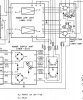
Board --> IMGP0689.jpg Schematic -->PSU AWR-001 circuit.jpg Circuit Layout -->PSU AWR-001 circuit board layout.jpg

05MAR17: Draft list created with specs from service manual.

06MAR17: The list was updated with proposed replacements and mouser part numbers.
08MAR17: Updated C9/C10 per LeeStereo's recommendation.
 
Last edited:
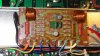
Anyone know how many QM-800A amps were built. Where is the serial number on these? I think I found a number on the left side of the chassis. #00007
I also see an engraved number on the back: C054-0

IMG_20170304_130006.jpg IMG_20170304_125241.jpg
 
Last edited:
Protection Unit 1 (AWM-028)


Location__|Specification___|Orig Size__|Replacement_|Repl Size_|Mouser #____|Qty |Notes________
C1/C2____|_0.056uf 50V_____|___________|____________|__________|skip________|__2_|_Mylar_______
C3/C4____|_470uf 6V________|_10x20_____|____________|__________|____________|__2_|_Electrolytic_
C5_______|_4.7uf 25V_______|_5x12______|_4.7uf 50V__|_5x11_____|UPS1H4R7MDD_|__1_|_Electrolytic_
C6_______|_100uf 16V_______|_10x13_____|_100uf 35V__|_8x12_____|UPW1V101MPD_|__1_|_Electrolytic_
Q1/Q2____|_2SC857K-A_______|___________|____________|__________|KSC1845FTA__|__2_|_Transistor___
Q3/Q4/Q6_|_2SC945-Q or R___|___________|____________|__________|KSC945C_____|__3_|_Transistor___
Q5_______|_2SA733-Q or R___|___________|____________|__________|KSA733C_____|__1_|_Transistor___
Q7_______|_2SC1384-R or Q__|___________|____________|__________|KSC2383YTA__|__1_|_Transistor___
D1-D8____|_1S2473__________|___________|____________|__________|skip________|__8_|_Diode________

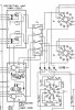
Board --> IMGP0692.jpg Schematic --> PU1 AWM-028 circuit.jpg Circuit Layout -->PU1 AWM-028 circuit layout.jpg
05MAR17: Draft list created with specs from service manual.

06MAR17: The list was updated with proposed replacements and mouser part numbers.
08MAR17: Fixed error it C3/C4 type.
 
Last edited:
Your set was designed and executed by the same team that produced the legendary SA/TX-9100. The TX-9100 is the tuner that will go well with your set. I have a similar set waiting in my inventory for restoration and relocation to a new home. Power is not high, but sound quality is. Good luck.

Enjoy,
Rich P
 
Protection Unit 2 (AWM-029)

Location__|Specification___|Orig Size___________|Replacement_|Repl Size_|Mouser #__|Qty |Notes________
C1/C2____|_0.47uf 25V______|____________________|____________|__________|skip______|__2_|_Mylar_______
Q1/Q2____|_2SC857K-A_______|TO-18,150V,50mA,0.2W|____________|__________|KSC1845FTA|__2_|_Transistor__
D1-D4____|_1S2472__________|____________________|____________|__________|skip______|__4_|_Diode________

Board --> IMGP0696.jpg Schematic -->PU2 AWM-029 circuit layout.jpg Circuit Layout --> PU2 AWM-029 circuit board layout.jpg
05MAR17: Draft list created with specs from service manual.

06MAR17: The list was updated with proposed replacements and mouser part numbers.
 
Last edited:
Power Amp Unit (AWH-015) X 2
I should only have to replace the capacitors, but I listed the transistors and diodes in case they test bad. I imagine some, if not all of these are probably unobtainium. I hope they will be within specification so I do not need to replace.

Location_____|Specification___|Orig Size__|Replacement____|Repl Size_|Mouser #__________|Qty |Notes________
C1/C2/C23/C24|_0.47uf 25V_____|_4x8_______|0.47uf 63V Film|7.2x3.5x9_|MKS2C034701C00JI00|__4_|_Electrolytic_
C7/C8________|_220uf 10V______|_10x17_____|_220uf 50V_____|_10x16____|UPW1H221MPD_______|__2_|_Electrolytic_
C9/C10_______|_.033uf 50V_____|_7x10______|_______________|__________|skip______________|__2_|_Mylar________
C11/C12______|_100uf 50V______|_13x20_____|_100uf 63V_____|_10x12.5__|UPW1J101MPD_______|__2_|_Electrolytic_
C19/C20______|_22uf 6V________|_5x12______|_22uf 25V______|_5x11_____|UKL1E220KDDANA____|__2_|_Electrolytic_
C21__________|_220uf 50_______|_15x25_____|_220uf 50V_____|_10x16____|UPW1H221MPD_______|__1_|_Electrolytic_
Q1/Q2/Q3/Q4__|_2SA726-GW or GY|___________|_______________|__________|KSA992FBU_________|__4_|_Transistor___
Q5/Q6________|_2SC1124-2 or 3_|___________|_______________|__________|skip______________|__2_|_Transistor___
Q7/Q8________|_2SC1157-D or C_|___________|_______________|__________|skip______________|__2_|_Transistor___
Q9/Q10_______|_2SA647—D or C__|___________|_______________|__________|skip______________|__2_|_Transistor___
Q11/Q12______|_2SC1402-R or O_|___________|_______________|__________|skip______________|__2_|_Transistor___
Q13/Q14______|_2SA744-R or O__|___________|_______________|__________|skip______________|__2_|_Transistor___
D1/D2________|_WZ-130 13V .5W_|___________|_______________|__________|1N4743ATR_________|__2_|_Zener Diode__
D3/D4________|_STV-4__________|___________|_______________|__________|skip______________|__2_|_Varistor_____
D5/D6/D7_____|_1S247__________|___________|_______________|__________|skip______________|__2_|_Diode________

Board --> IMGP0701.jpg Schematic --> POWAMP AWH-015 schematic.jpg Circuit Layout --> POWAMP AWH-015 circuit.jpg
05MAR17: Draft list created with specs from service manual.

06MAR17: The list was updated with proposed replacements and mouser part numbers.
 
Last edited:
Filter Caps, VU Caps, and Relay
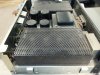
I would like the filter caps to match the diameter if at all possible. I read about some restorations cutting open the caps and placing them over a smaller replacement cap.
Since the VU caps are Mylar, I would think they are ok.
I plan on replacing the relay to make sure it is fresh.

Location_____|Specification___|Orig Size__|Replacement_|Repl Size_|Mouser #|Qty |Notes_______________
C1/C2/C3/C4__|_.1uf 50V_______|___________|____________|__________|skip____|__4_|_Mylar______________
C5/C6/C7/C8__|_4700uf 50V_____|_40x60_____|____________|__________|________|__4_|_Electrolytic_______
S7___________|_S61-007-0______|_20x27x35__|____________|__________|________|__4_|_Relay Omron Type 4 lugs

Filter caps Photos --> IMGP0702.jpg pf - 3.JPG pf - 4.JPG Schematic --> filter caps schematic.jpg
Relay Photos --> relay top.jpg relay bottom.jpg Schematic --> relay.jpg

05MAR17: Draft list created with specs from service manual.
06MAR17: The list was updated with proposed replacements and mouser part numbers.
 
Last edited:
VU Meter Lights
So I replaced the burned out 8V fuse lamps with Warm white Fuse LEDs. I am pleased that they lit up without any issues. Since the back of the VU meters are very yellow, the white/yellow light mixed with the blue makes the display greenish.

Warm White LED and VU meters.
I think it looks ok. It has a yellow light around the border and greenish color. I may order some blue leds and see if they look ok in there.
VU3.jpg

Yellowing on the back of the VU meter from years of hot fuse lamps and aging plastic. Is there any way to 'clean' or treat the plastic to make it white?
VU Yellow.JPG
 
I need to come up with a recap/restore list. I can replace the capacitors with like for like specified in the service manual. I usually go up in voltage, but I notice sometimes capacitance is increased on filter circuit capacitors. Does this make it perform better?
A bit, increased capacity will filter hum better to a point.

you are asking for a fair bit of work to be done. But you are fortunate, some of the work has already been done.

I bought a qx-9900 recently. So I am somewhat in the same boat as you. Now that I compare with the pcbs in your QM-800A, I see many are identical to the qx-9900. The qx-9900 is working pretty good, except for the switch gang for the tuning meter lamps/function lamps is a problem. to many years of running a high current through those contacts, they are fried. I think I will replace the lamps with LED as you have done to ease the stress on the contacts. It is a major PITA to fix the switch, I even have a spare, but it is a ton of wires to remove and re-solder in a very tight spot.
Someone posted a BOM for the qx-9900 a while ago and I have been working on it with my changes. I will attach it for you to use. It is not complete but in pretty good shape.
http://audiokarma.org/forums/index.php?threads/pioneer-qx-9900-recap.631800/

I have not done the work so there maybe some errors.

Based on the qx-9900 operation, I think that I will change and suggest to you to just change ecaps, leave the bjts/diodes alone for now since mine is noise free and sounds just fine. I was planning to do some measurements on the stock unit before I do any changes. Just so I have something to compare against after I do some re-firb.
I did notice on my qx-9900 that the plastic screws fastening the TO-220 bjts to the heatsink were disintegrated, so I had to remove the heatsink, drill out the old plastic and replace with new mica, metal screws/nuts, shoulder washers. I'd check your PS pcb to see if it has the same problem. It is not the same pcb as the qx-9900, but it might be assembled the same.

I have not measured the big ecaps, they might be just fine. if I measure them I'll let you know.

I have put down a few options for parts to be used. if you can fit the film caps, I suggest to use them. I would not replace existing mylar caps, there is no need to. Let me know what other assy's are used, they also maybe the same.

Main Amp Unit AWH-015

C1 0.47 25v cssa 505-MKS2D034701E00JSSD 80-R82EC3470Z370K 667-ECQ-E2474KB3 647-UKL1HR47KDDANA 647-UKL2AR47KDD
C2 0.47 25v cssa
C23 0.47 25v cssa
C24 0.47 25v cssa
C7 220 10v cea (D=10x18mm 647-UES1C221MPM 647-UPW0J220MDD 647-UPW1A221MED
C8 220 10v cea
C11 100 50V cea 647-UPW1H101MPD
C12 100 50V cea 647-UPW1H101MPD
C19 22 6.3v cea
C20 22 6.3v cea 647-UES1C221MPM 647-UES1C221MPM1TD
C19 22uf 10v electrolytic (on board 10V) 647-UPW1A220MDD 647-UPW0J220MDD
C20 22uf 10v electrolytic (on board)
C21 220 50v cea 647-UPW1J221MPD6 UPW1H221MPD
D1,2 WZ130 13.0V 1/2W 5% DO-35 512-1N5243BTR 78-BZX55C13 78-BZX55B13-TAP 78-TZX13C
D5,6,7 1S2473 512-1N4148
Q1 2sa726-gw(bce) 512-KSA992FBU (Vbe/hfe match to Q3)
Q2 2sa726-gw 512-KSA992FBU (Vbe/hfe match to Q4)
Q3 2sa726-gw 512-KSA992FBU
Q4 2sa726-gw 512-KSA992FBU
Q5 2sc1124-2 (Sony:180V,1A,1W,35MHz,hfe=40min@20mA) TO-202N(NTE190),ebc
Q6 2sc1124-2 512-KSC3503DS
Q7 2sc1157-d (Mitsubishi:100V,0.8A,7W@Tc=25,70MHz,hfe=20-300@300mA) TO-202N(NTE???),bce
Q8 2sc1157-d 512-KSC3503DS
Q9 2sa647-d (Mitsubishi:100V,0.8A,7W@Tc=25,70MHz,hfe=20-300@300mA) TO-202N(NTE???),bce
Q10 2sa647-d 512-KSA1381ESTU
Q11 2sc1402-r Sanken, 80V,8A,70W,10MHz,hfe=30min@3A,TO-3
Q12 2sc1402-r 863-MJ21194G npn output, 250V,16A,250W,4MHz,TO-3 ($6.52)
Q13 2sa744-r Sanken:80V,8A,70W,15MHz,hfe=30min@3A,TO-3
Q14 2sa744-r 863-MJ21193G pnp output. 250V,16A,250W,4MHz,TO-3 ($6.52) (SOA: 2.5 A, 80 V, 1 Second)
VR1,2 4.7K Offset 652-3386H-1-472LF
VR3,4 100 Bias 652-3386H-1-101LF bias 100 ohm 1 turn
534-4662 to-3 mica insulators

Protection Unit 1 AWM-028

C1 0.22uf 10v electrolytic. (on board) 80-R82DC3220DQ60J
C2 0.22uf 10v electrolytic. (on board 80-R82DC3220DQ60J
Additional 2.2 uf 35v (tacked on foil side of board)
C3 470 6V cea 647-UPW0J471MPD 647-UVP1C331MPD (replaces C3,C4, short one of them out, or jumper across)
C4 470 6V cea 647-UPW0J471MPD
C5 4.7 25V cea 647-UPW1E4R7MDD
C6 100 16v cea 647-UPW1E101MED
Q1 2sc857k-a 512-KSC1845FTA
Q2 2sc857k-a 512-KSC1845FTA
Q3 2sc945q 512-ksc945c
Q4 2sc945q 512-ksc945c
Q5 2sa733q 512-ksa733c
Q6 2sc945q 512-ksc945c
Q7 2sc1384-r 512-KSC2383YTA (Vce=160V,Ic=1A,Pd=900mW,Ft=100M,hfe=60-320,TO-92L,ECB) $0.59
512-KSC2690AYS

Protection Unit 2 AWM-029

Q1 2sc857k-a 512-KSC1845FTA (TO-18,150V,50mA,0.2W)
Q2 2sc857k-a 512-KSC1845FTA

Chassis:

C3 4700 50v ACH-16-A
C4 4700 50v ACH-16-A
C5 4700 50v ACH-16-A
C6 4700 50v ACH-16-A
Outer Dimensions 1-5/8"(40mm) x 2-1/2"(63.5mm).
647-UVR1H472MRD Aluminum Electrolytic Capacitors - Leaded 50volts 4700uF 20x40 20% 10LS
647-LKG1H682MKNS 40mm(D)x80mm(L) Aluminum Electrolytic Capacitors - Leaded 6800uF 50 Volts 20% Tol
598-383LX822M080N052 40mm(D)x50mm(L)Aluminum Electrolytic Capacitors - Snap In 8200UF 80V

Relay I am not sure, exactly what to use, it could be with stand offs

Relay(S6):ASR-003-0 DAIICHI 24VDC 4PDT 653-LY4F-DC24 653-MY4F-DC24
standoff from mouser 15mm need two per side: 728-FM2110-3005-A due to TOP ears!!
728-FM2110-3005-A is 4.5mm od 3mm x 0.5 thread 15mm male female aluminum 0.63 /100: 0.43
728-FM2110-3005-SS is 4.5mm od 3mm x 0.5 thread 15mm male female stainless steel 1.07 /100: 0.74
728-FM1262-3005-A is 4.5mm od 3mm x 0.5 thread 15mm female female aluminum 0.59 /100: 0.40
728-FM1262-3005-SS is 4.5mm od 3mm x 0.5 thread 15mm female female stainless steel 0.97 /100: 0.67

Good Luck
Rick
 
I have not measured the big ecaps, they might be just fine. if I measure them I'll let you know.

I have put down a few options for parts to be used. if you can fit the film caps, I suggest to use them. I would not replace existing mylar caps, there is no need to. Let me know what other assy's are used, they also maybe the same.

Rick,
I want to thank you for posting this. It was a huge help. I would have never known that the qx-9900 shared common boards. I went through and updated the lists above with replacement electrolytic capacitors and the mouser part numbers. Luckily I have most of the ecaps available from previous orders to Mouser where I ordered more for the price break. I plan skip the mylar caps, diodes, and transistors listed as 'skip' at this point.

Again, thanks for the helpful information.
 
...I need to come up with a recap/restore list. I can replace the capacitors with like for like specified in the service manual. I usually go up in voltage, but I notice sometimes capacitance is increased on filter circuit capacitors. Does this make it perform better?...

I posted this response to a very similar query in the Sansui forum: "Generally, there is no problem increasing the capacitance rating of the local decoupling/filtering capacitor (especially for small values less than 1000µF). IMO, a 2X-3X increase is acceptable for most small capacity capacitors whose purpose is solely DC filtering. In these cases, the extra load on the power supply transformer and diodes is inconsequential. For the AU-919, consider that the combined increase in capacitance of the small board capacitors is ~6,000µF, which is only 10% of the combined capacitance of the main power capacitors (4 x 15,000µF). More often than not, the original capacitance rating specified during manufacturing was often limited by capacitor technology of the day, the cost of component and the physical size (finite space available on the PCB). For example, the driver board local decoupling capacitors specified in the Sansui AU-7500 are 100µF/50V (12.5mm diameter), whereas those in the more powerful AU-9500 are only 47µF/80V (12.5mm diameter); the determining factors in this example is the available physical board space with then current capacitor technology rather than cost since the AU-9500 was a TOTL model.

Why increase the capacity of a power supply? It can be argued that the power supply is in the signal path, it's essentially in series with the output stage and hence does impact the sound of an amplifier. Nelson Pass uses the analogy of a water reservoir as the power supply and the output stage as the valve that controls the flow of the water: https://www.passdiy.com/project/articles/power-supplies. If you have a poor and/or inadequate supply, the quality and/or the quantity of water is affected. For an amplifier, a poor/failing power supply capacitor (e.g., low capacity, high ESR) may not be able to supply the voltage/current that the output stage is "asking" for. IMO, this is primarily why improving the power supply (e.g., increasing capacity, lowering impedance/ESR) often does impact/improve the sound of an amplifier."

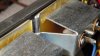
For example, for C9/C10 on AWR-001, consider using 220µF/50V. In your list, you label C3/C4 on AWM-28 as "mylar", but this is surely an error as they are 470µF/6.3V electrolytics; they can be replaced by a single 220µF bi-polar electrolytic type (since they are in series to mimic a bi-polar one), but remember to install a jumper in the "empty" location (this upgrade has already been noted by @rcs16 above). The original main filter capacitors are 40mm in diameter and appropriate same size replacements are hard to find these days, but judging from the picture of the gap in the mounting clamp closure, a 35mm diameter replacement may fit, e.g., 661-EKMH500VNN822MA.
 
For example, for C9/C10 on AWR-001, consider using 220µF/50V. In your list, you label C3/C4 on AWM-28 as "mylar", but this is surely an error as they are 470µF/6.3V electrolytics; they can be replaced by a single 220µF bi-polar electrolytic type (since they are in series to mimic a bi-polar one), but remember to install a jumper in the "empty" location (this upgrade has already been noted by @rcs16 above). The original main filter capacitors are 40mm in diameter and appropriate same size replacements are hard to find these days, but judging from the picture of the gap in the mounting clamp closure, a 35mm diameter replacement may fit, e.g., 661-EKMH500VNN822MA.

Thanks for your input on this, and thanks for pointing out the error I had on AWM-28. I corrected it in post #6 above.
As far as the main filter capacitors. I have a cheap capacitor tester, and I plugged it onto the 4 main filter capacitor (after making sure they were discharged). I think they test good. But can you get a good test reading while they are in circuit?

Thoughts?
Item___| C 5 _| C 6 _| C 7 _| C 8
Vloss% | 2.3% | 1.6% | 1.9% | 1.6%
uF_____|5076uF|5517uF|5481uF|5475uF
ESR ohm| 0.00 | 0.02 | 0.00 | 0.00
 
I think that you proved that you can and what I suspected that they are still good and do not require replacement unless you want to spend the money and upgrade them. btw Mouser has a few 40mm diameter ecaps to chose from.
I do not believe that they used a bleeder resistor which would throw the measurements off. As an upgrade you could put a small film across them, 1uF,100V would do, it just helps with higher freq filtering.
 
Back
Top Bottom