• The move to the new server is done. There are some software and database maintenance updates in process. This has us passing the hat around to help out. We appreciate any donations. Seriously, even a dollar helps. The payment page may be found here - https://www.audiokarma.org/support.html

Pioneer RT-707 recording problem

SolderSplash

New Member
After reading this excellent thread, I was able to replace the counter belt and a few noisy transistors in the input amp. Now the LINE IN sounds great on the headphones, and passes through to LINE OUT very cleanly.

The problem: Playback amplitude and frequency are good, but I can hear a low-level, intermittent dropout. It's kind of random at a few Hz.

Symptoms:
  • There is absolutely no dropout in the source from the Headphones or LINE OUT.
  • The tape passes over the heads perfectly; there is no skew, and pressing lightly on the tape, near the heads, has no effect on the recording.
  • Playing the same section over again has the same dropout pattern, so I'm pretty sure the dropout is in the recording.
I'm a relative noob to audio repair, but I've enough electrical experience and equipment that I could spot the noisy transistors in the input amp. I have followed this recording signal all the way through to the recording head, but I'm not sure what to look for.

I have found some noise in the power supply, and I currently suspect the Zener that's used in the regulation portion. But I wouldn't recognize noisy capacitors if they slapped me. Or could it just be the old tape I'm using?

Here's the regulation circuit:

RT-707%2BPower%2BOSC%2BSchem.jpg


Here's what Vin (~44V) and Vout (aka B+, about ~31V) look like, when STOPPED:
RT-707%2BTrace%2B07%2Bstop%2BQ307-C%2BB%252B.JPG


... and when RECORDing:
RT-707%2BTrace%2B06%2Brec%2BQ307-C%2BB%252B.JPG

I think I was recording a -7dB 440Hz signal.

There is a test point, just before the recording head in the OSCILLATOR block of this diagram, cleaned up for older eyes, and a few errors corrected (click to enlarge):


At TP301 (yellow) and B+ (blue) when STOPPED:
RT-707%2BTrace%2B10%2Bstop%2BTP301%2BB%252B.JPG


...and when RECORDing:
RT-707%2BTrace%2B12%2Brec%2BTP301%2BB%252B.JPG


At some time scales, you can see that the noise is making through to TP301:
RT-707%2BTrace%2B11%2Brec%2BTP301%2BB%252B.JPG


Even closer:
RT-707%2BTrace%2B13%2Brec%2BTP301%2BB%252B.JPG


So, am I barking up the wrong tree? Caps, Zener, Tape or what?

Thanks!
 
Register to hide this ad
Hi,
first thing is to check that the erase oscillator is stable. As you have a scope, get a 10X probe, so that you don't load the test point too much. Check the voltage on the connection at the rear of the erase head. The left channel should be easy to get at. The right may be more tricky. If this is unstable amplitude wise it will show up on recordings as this also produces the recording bias. If there is instability, the first things to rule out are bad connections. There are lots of them. The 2 relays for Record selection, the Bias Switch and the speed switch. The equalisation switch is also a contributor but that will only affect the audio signal at TP301 (L Ch).

With the machine powered, select both record selectors. Hold in the stop button and repeatedly push and release the record button at least 20 times. This has to be done slowly as there is a delay associated with the record selection. The relays are held in for a while to let the Erase Oscillator die away. This helps to stop magnetisation of the record and erase heads when the machine is stopped from recording. Initially, try 1 sec in/ 2 sec out (that sounds rude!!!). This will help to clean the contacts of the record relays.

With the machine unpowered (you will drive the speed Servo PCB daft here), repeatedly change the state of the Speed, Bias and Equaliser switches. Following this try the machine again and see if things have improved. This routine kept my machine good working order for over 25 yrs without having to resort to any switch cleaner of any kind. If the switches are move regularly they ten to self clean.

See how that goes.

GPS16
 
first thing is to check that the erase oscillator is stable.
Well, it looks rock-solid:

RT-707%2BTrace%2B17%2Berase%2Bhead%2Brec%2B466Hz.JPG

Is it supposed to be 112Vrms at 115kHz? That's pin 33 with trace persistence on. The record head signals look just as clean (8.6Vrms), at pins 36/37. The schematic:


But test points 301/302 (top center) have a jitter and unstable amplitude you can see (trace persistence on) that "kinda" matches the dropout pattern I'm hearing:

RT-707%2BTrace%2B16%2BTP-302%2Brec%2B466Hz.JPG


The input at pin 14 is pretty clean, coming from the LINE IN amp. I still suspect that the noise in the 32V rail gets amplified by Q301 and again by Q303.

I don't think it's the tape, but I'm not sure how to test it. I found a distinctive drop-out, and recorded several times to see if it was at a particular spot, but the dropout seems pretty random.

Suggestions?
 
You say it's a periodic dropout (a drop in volume) and then later you say it's a periodic noise. Those are different. Which is it? It would be "noise" if you put the deck into record and heard the "problem" with no audio inputted.

You did not tell us brand, model, age of the recording tape. Do all of your recording tapes do the exact same thing? You always need new, good tape when fixing a tape deck (like RMG/Pyral SM911).

Sounds like a tape path issue like a bad pinch roller, bad tape or uneven rec head wear. Drag you hand on the left reel while in REC and see if that changes things.

If you want to observe the audio signal that goes to the rec head, lift R702 and put deck into REC. Put scope probe on the REC head hot. Tap on the record relays 301,302 to see if relay contacts are good. If audio is clean and steady, then it's a tape path mechanical problem. .
 
Last edited:
You say it's a periodic dropout (a drop in volume) and then later you say it's a periodic noise.
The dropout is what I hear in the audio output (headphones and line out). It sounds like a random, momentary muting, maybe a few Hz. With no input, I can barely hear ticks, but they're not very sharp.

I found noise in the "regulated" 32V rail (Q307 emitter). The rectified 44V looks clean. I can trace that noise all the way to TP301/302, where the signal (at a much larger scale) also shows jitter and amplitude drops.
Sounds like a tape path issue like a bad pinch roller, bad tape or uneven rec head wear.
Well, the tape seems to be rolling through very nicely. It doesn't wander, that I can see. I tried using a swab to make the tape conform to the head a little more, but it really didn't affect the sound. Light pressure on the supply reel doesn't affect anything, not even the speed.

The pinch roller was in decent condition, but it needed a little scuffing and Rubber-Renue. With light pressure on the supply reel, there is no slippage.

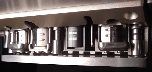
Do the heads look ok?

Pioneer%2BReel-to-Reel%2BTape%2BDeck%2BRT-707%2B08a.JPG


Close-ups of the record head:

(clickable)

Tap on the record relays 301,302 to see if relay contacts are good.
Yep, no noise or bounce. A sharp rap produces a low-level "whomp".

You did not tell us brand, model, age of the recording tape... You always need new, good tape when fixing a tape deck (like RMG/Pyral SM911).
DAK enterprises. 1982? Blech? It's the only tape I have. Who's your favorite supplier? Is this ebay listing ok?

If you want to observe the audio signal that goes to the rec head, lift R702 and put deck into REC. Put scope probe on the REC head hot. If audio is clean and steady, then it's a tape path mechanical problem.
With the REC L and REC R switches off, right? Hmm, what does that do? This is to see the unmodulated signal at the dummy head? Lifting R702 stops the erase oscillator so its just the raw audio?

Thanks for the guidance.
 
Last edited:
There is no dummy head. The idea is to look at the audio signal at the record head, so to do this you have to turn off the bias OSC (lift that resistor). Then you put the deck into record mode. Record mode means the record switches need to ON (not off as you said). Look for clean, steady audio. Tap on the record relays. Turn record switches on/off to see if they make good contact. Now kill the audio input and see if any noises at the record head.

Then you can look at the bias signal at the same spot (record head): reconnect that resistor and with no audio input put deck into record. Look for clean, steady bias signal. Tap on two relays and turn record switches on/off to see if they make good contact.

Don't buy the new tape from eBay. Buy from the many authorized dealers (stores) like Full Compass.

See if the period of the record dropout changes with speed. If it does, then it's a mechanical tape path issue. See if the dropout is in sync with the pinch roller rotation.
 
Last edited:
Great explanation, tapetech.
See if the period of the record dropout changes with speed.
I can't tell a difference. I think there might be more audio noise at slower speeds, but the amount of amplitude drop, how often it drops and the duration of the drop seem just as random.
See if the dropout is in sync with the pinch roller rotation.
Definitely not. The gap between the biggest and longest drops is several revolutions... usually.

I'll get the audio and bias signals isolated next.

Thanks!
 
Hi,
keeping an eye on this thread but keeping stum at the moment. Don't want to tread on TapeTechs toes. Must admit that I don't like the spikes on the blue traces!!!

GPS16
 
I'm also wondering about Q1201-Q1208 on the EQ board. They are the same kind of transistors that have failed elsewhere, and the bases are driven by the noisy B+ when selected. That's through a 47K, and a .01u to ground, so that should be filtered out, but... Maybe they've gone noisy? That's just another reason to look at the isolated bias and audio signals.

BTW, when I first started looking around, many of the components I checked were marked. There was red marker on a fuse that blew (FU6, attributed to my clumsiness), black marker on two PS caps, and a white dot on a replacement transistor. I didn't realize it when I started, but now that I've had a good look around, the markings seem coincidental.
 
Last edited:
Instead of lifting R702 on the SWITCH ASSY, I unwound the wire jumper from pin 62 to 11, which also cuts power to the bias oscillator. With 1500Hz LINE IN, this is pin 36 on the POWER & OSC board, which goes to the Recording Head (L):

RT-707%2BTrace%2B19%2Brec%2Bhead%2Bbias%2Boff.JPG


Is it just me, or does that look like ####? :rant: The amplitude on that drops randomly, just like what I'm hearing.

Starting back at the input to this board, pin 14 looks good:

RT-707%2BTrace%2B22%2BP14%2B1500Hz%2Bbias%2Boff.JPG


Through VR301 to the base of Q301, it's attenuated but not too noisy:

RT-707%2BTrace%2B24%2BQ301B%2B1500Hz%2Bbias%2Boff.JPG


Then at the collector of Q301, which is drawing from the noisy B+, it's nasty:

RT-707%2BTrace%2B25%2BQ303B%2B1500Hz%2Bbias%2Boff.JPG


Smoothed and amplified at Q303's collector, it has some distortion:

RT-707%2BTrace%2B26%2BQ303C%2B1500Hz%2Bbias%2Boff.JPG


The noise does not look as significant to the 600mV amplitude. But when it gets attenuated by R317, it is significant again (and nasty again). Aaaand we're back to TP 301, which looks pretty much like first trace of what goes to the recording head.

FYI, the collectors of the EQ board transistors Q1201-1208 (pins 301 and 302) look like this:

RT-707%2BTrace%2B27%2BEQ301%2B1500Hz%2Bbias%2Boff.JPG


Their bases are tied to (EQ-switched) B+ through 47K, and to ground through 0.01u.

It sure seems like the noise affects the Q301/Q303 current driver, and although it gets smoothed, the attenuation at R317 means the noise is significant.

I wonder though... are Q1201-1208 noisy, and they're affecting the PS, or is the PS noisy, which affects the small signals? Is it a bad PS cap? I have no idea what a bad cap would do to B+.
 
Hi,
The 4 Eq transistors are not going to affect the supply. They are acting as switches in the feedback loop for Q301/Q303. Any problems there would need to go backwards through a 47K resistor. You have also not mentioned that the problem is at just one speed or Bias/Eq setting. The likelihood of all 4 transistors being faulty are slim. The spikes on the power supply do not look good. That is supposed to be a regulated supply. If I were you I would get rid of the spikes and take things from there. Try looking closer to the emitter of Q307 and start changing modes. Are the spikes there during stop mode, if not what is the machine doing when they appear. What switches are changed state to induce the spikes. And so on..... I would also check the continuity of the connections from the emitter of Q307 to the resistor R303 (not the end at the collector).

GPS16
 
Are the spikes there during stop mode
Yep, that's one of the first things I checked, to see if it had to do with loading. From my first post:

RT-707%2BTrace%2B07%2Bstop%2BQ307-C%2BB%252B.JPG


That's rectified (yellow at Q307C) and "regulated" B+ (blue at Q307E) when STOPPED. I have replaced Q308, so that leaves Q307, the 7V Zener or maybe C322. I've been putting off pulling C322 because it's fairly large for my cheap ESR meter-slash-transistor tester. :( Perhaps it could it be C323, which smooths the Zener.
[Is] the problem... at just one speed or Bias/Eq setting
I think I tried them all and decided they didn't matter, since the noise is present when STOPPED. I'll double-check.
check the continuity of the connections from the emitter of Q307 to the resistor R303 (not the end at the collector).
Thanks, another good suggestion!
 
Confirmed: BIAS, SPEED, RECORD and PLAY don't affect B+. There's always a periodic ~13mV spike and a fairly constant 5mV noise level.

I checked continuity along B+. R303 is next to pin 13 at the right middle edge:

(clickable)

I inspected all the solder joints when I replaced Q301-Q304 and Q308.
If I were you I would get rid of the spikes and take things from there.
I would really like to do that! :)
 
Hi,

The components around the series regulator definitely need some further investigation. C324 needs adding to the list. It is of the right value for high frequency noise suppression. The other one is the cap in parallel with the 470u one, C321. The voltage on the zener ZD301 should be clean. If there is noise there it will get transferred as it is the reference.

Keep going. You have a real meaty fault here. There will definitely be a well done due when you have cracked it.

GPS16
 
Pbbbbth! What a surprise, the Service Manual doesn't match the PCB... the circuit is the same, but the layout is a little different:

RT-707%2BPower%2BOSC%2BPCB%2Bchanges.jpg


I kept looking at the component side and couldn't match it with the SM PCB. Duh.

After pulling caps C321, C323 and C324, they all tested ok. Next, I tested the 7V zener by itself on a breadboard:

RT-707%2B30%2BZD301.JPG


Thar she blows! It triggers at 8.2mV, and the spike occurs at about 80kHz. The trace above is without a parallel cap. With C323 (or a replacement) in parallel, the spike is the same, but the lower-level constant noise is a little reduced:

RT-707%2B30%2BZD301%2B%2526%2Bcap.JPG


The old zener tests at 7.19V @ 2.2mA, which is close to the in-circuit current of about 3mA. My stash of Zeners only has 6.8V and 7.5V, so I tried a 3.3V in series with a 3.9V. At this low current, that pair only gets to ~5.2V. I'm a little concerned that dropping a different Zener in here will require adjustment of several things down the line, so I'd really like to reproduce the 30.94V I measured at B+.

I think I'd like to drop in a TL431 Precision Reference (aka "adjustable Zener"):

RT-707%2BPower%2BFix%2B1.JPG


Instead of the 1.1K resistor, I'll drop in two standard resistors and a 100Ω pot to dial in B+. The 330R & 560R keep the adjustable voltage between 25V and 32V, just to be safe! TL431s don't like a capacitive load at this current, so C323 can be deleted. Their noise levels are much less than Zeners, so that should help as well.

The simulation looks good, but is there anything else I'm missing?

Thanks!
 
Hi,

Congratulations on finding the culprit. Without a scope that would have been a stinker!!!

Once you have a clean and stable 31V, take things from there. Hope the drop outs witnessed were due to this.

Well Done!

GPS16
 
In message 14, you say the first scope photo (of the head signal) drops in level randomly, but when you posted the photo of TP 301, you did not indicate if the signal was steady or drops in level. Please indicate. If steady, then you have a bad record relay.

Re noise: could be a bad ground. On the POWER/OSC board, be sure pin 4 goes to chassis. Connect a clip lead from pin 4 to the chassis. If no improvement, connect the clip lead from chassis to various grounds throughout the deck to see if that gets rid of noise on the DC line.
 
Message 14 is just the PCB image. In message 11, I posted this:
The amplitude on [the recording head] drops randomly, just like what I'm hearing.
RT-707%2BTrace%2B19%2Brec%2Bhead%2Bbias%2Boff.JPG

In message 3, I posted this:
But test points 301/302 (top center) have a jitter and unstable amplitude you can see (trace persistence on) that "kinda" matches the dropout pattern I'm hearing:
RT-707%2BTrace%2B16%2BTP-302%2Brec%2B466Hz.JPG
...so I think the amplitude issue is at both TP301 and the recording head. There is no jitter like I first thought. It was just a bad trigger choice.
...could be a bad ground. On the POWER/OSC board, be sure pin 4 goes to chassis...
Wow, never considered that. I'll check...

Thanks!
 
I would jumper the record relay contacts to eliminate that as a problem. Bad contacts could cause level variation at TP 301 as well as at the head.
 
Back
Top Bottom