• The move to the new server is done. There are some software and database maintenance updates in process. This has us passing the hat around to help out. We appreciate any donations. Seriously, even a dollar helps. The payment page may be found here - https://www.audiokarma.org/support.html

Pioneer SA 6500 II - recap gone wrong

robiles

Active Member
Hello all,

i have a Pioneer SA 6500 II amp - in perfect working condition before today - that i tried to recap mostly because i have a lot of free time on my hands, and because i like to thinker with things (this is my first such project).

Hade all my homework, procured all the things that i needed, while triple checking all ordered parts. Today i started to change caps, and all worked perfectly until i was done and wanted to try it out - to my surprise no sound came out of the speakers.

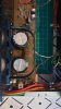
After a close inspection i discovered that a cap, c69 to be precise, was mounted the other way around. I was hoping that this caused no damage (an as far as i can see, it did not to the cap itself, or to other caps), and turned it around, and tried the amp out again. Now it did work, but badly - has distortion, something like static noise, scratchy lows and highs (if that makes any sens).

Now it is time to kindly ask for help from lnowledgeable forum members, with ideas to what i can do to repair the amp. As this is a pretty basic and cheap amp, i would like to do it myself. I do not have the necessary equipment yet, bit will buy what is needed in the near future.

I wil start off with reading "Troubleshooting electronics without tears" but any additional help is more than welcome.

Thank you all in advance.
 
Register to hide this ad
Nobody out there who can lend a helping hand?

To continue my quest on "repairing" the amp, i have bought a DMM and started measuring voltages as good as i could, and i found a couple that are not even close to what they are supposed to, and those are Q17 and Q18 (edit: lower leg with -0.5V instead of -34V(-29V)). There is also the Q27, the lower leg registers -8.2V instead of -5V (no idea if relevant). I have compiled all the data in a pdf file, but it is too large to upload - but could e-mail it if anybody is willing to help.

Now i do not know if these are the parts that need replacing, but was thinking about desoldering them, and introduce them in my brand new TC-1 Tester to see what is says. Other than that i am clueless.

Any help is apreciated.
 
Last edited:
If not already done. Check for solder bridges. Lifted traces, loose or disconnected wires.

The distortion is in both channels?
 
The cap may have been damaged by the wrong insertion also.
Have tried another new one?
 
If not already done. Check for solder bridges. Lifted traces, loose or disconnected wires.

The distortion is in both channels?

I thoroughly examined all the solders that i have done, and they all seem decent, but there are some scratches on the green coating of the board, but those were present before i started working on it. Distortion is in both channels and both speakers sound the same. After realizing my mistake i replaced the switched cap with the one that i took out (before that there was no sound at all). As a layman with problem solving skills, i think i may have damaged one or more components other than the wrongly placed cap.
 
UM . . . canofworms-538x218.png

First: NEVER reuse an electrolytic capacitor that has been powered up backwards, always replace it. It HAS been damaged and is just waiting to fail. Same for transistors.
Second: Recheck everything you did, you got one in backwards, there are likely more, plus you may have damaged other parts.
Third: Removing small, low cost parts to just test them, is a waste of time, and just as likely to cause damage to the part or the circuit board. If you remove them replace them. Be very careful, some replacement parts (like transistors) have different lead orders than the originals
Build or acquire a DBT: Dim Bulb Tester diagram pictorial... please feel free to copy and post.
Study this: Bipolar Junction Transistor Testing Basics
Welcome to Audiokarma, don't be discouraged, this is a hard way to start off, with a good unit damaged by your first time working on it. Everybody makes mistakes.
 
Last edited:
Check C57, C58 (6800µF, 42v) for installed backwards, if you changed them, check fuses FU3, FU4 with ohmmeter for being blown.
 
Last edited:
Check C57, C58 (6800µF, 42v) for installed backwards, if you changed them, check fuses FU3, FU4 with ohmmeter for being blown.

Bullseye, both fuses are blown, checked them with a dmm and visually - but the C57 and C58 caps are actually correctly installed (i have double and tripple checked all caps). Might the blown fuses be the problem and nothing else? Are these normal fuses that can be bought anywhere (respecting specs, of course)?

edit: i have uploaded a photo of c57 and c58 caps as installed, and to me they look correctly installed.
 

Attachments

  • 15966915817542225559868307599234.jpg
    15966915817542225559868307599234.jpg
    75.3 KB · Views: 32
Last edited:
Yes they are common fuses, but don't use 32v automotive fuses. The ones in there are probably rated 125v or so, look in the SM.
Something caused those fuses to blow. The speaker protection circuit in this amp is call a "crowbar circuit" because it acts by brute force, D15 is triggered (becoming a short circuit) by a failure at the output transistors, dumping the charge from C58, pulling massive current through D3 and D4, and blowing the fuses. All the power available from the power supplies is cut off and pulled away from damaging the speakers and is dissipated by R100 and D15. The protection circuit monitors the power amp outputs for dc voltage through R101 for the left channel and R102 for the right channel, through a low pass filter of C76 and C77, pulling Q24 or Q25 into conduction, which fires Thyristor D15.
Your backwards C69 disrupted the delicate balance of the differential amps (Q7, Q9 & Q8, Q10) causing huge dc offset at the outputs. You might get lucky and find just the fuses and C69 are the extent of the damage. Buy some extra fuses just in case, and get a DBT before you turn the power on again. Test all the transistors in the output stage, also..
 
Yes they are common fuses, but don't use 32v automotive fuses. The ones in there are probably rated 125v or so, look in the SM.
Something caused those fuses to blow. The speaker protection circuit in this amp is call a "crowbar circuit" because it acts by brute force, D15 is triggered (becoming a short circuit) by a failure at the output transistors, dumping the charge from C58, pulling massive current through D3 and D4, and blowing the fuses. All the power available from the power supplies is cut off and pulled away from damaging the speakers and is dissipated by R100 and D15. The protection circuit monitors the power amp outputs for dc voltage through R101 for the left channel and R102 for the right channel, through a low pass filter of C76 and C77, pulling Q24 or Q25 into conduction, which fires Thyristor D15.
Your backwards C69 disrupted the delicate balance of the differential amps (Q7, Q9 & Q8, Q10) causing huge dc offset at the outputs. You might get lucky and find just the fuses and C69 are the extent of the damage. Buy some extra fuses just in case, and get a DBT before you turn the power on again. Test all the transistors in the output stage, also..

Thank you for taking the time to compose such a detailed answer, i will read your post a few times, until i process what you wrote there.

Already found, and will be ordering a 10-pack of fuses (125v 5a as stated in the diagram), and will follow the other steps mentiond in the post until the fuses arrive.

Now i have a couple of questions that might be stupid, but i hesitate on doing anything until i am certain that what i do is correct:

- can transistors be tested while mounted on the board? (and tested as described in the link you provided earlier)

- i have no idea which transistors belong to the output stage, and hould be really helpful if you coul give me a hint how to identify them (i am trying to learn as much as i can, and not have all the answers delivered on a silver plate)

Thank you again for your help - large quantities of beer will be drunk in your name.
 
Do you have the service manual? Make sure you grab a copy of it, hifi engine is free and should have it.
Build that dim bulb tester you definitely need it.

Take plenty of pictures and post them here, it may help the troubleshooting
 
Parts for dim bulbs tester have been purchased (have to look in the basement for a light bulb, as they are banned in Europe atm), and proper fuses have been ordered. Once all is done, i shall let you all know how it went.

As soon as i am home i will take a photo of the amp in it's current state, in case anybody want to take a look at it.

Thank you all for your help, it has really lifted my spirit.
 
You are welcome!
Transistors can be tested in circuit, but sometimes the surrounding components affect the measurements. If they fail the transistor testing they are bad, but just because they pass the 'diode test' does not guarantee they are good.
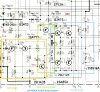
Here is a snapshot from the schematic of the power amp section of the SA-6500II:
annotated_output-stage-SA-6500II.jpg

This is the left channel, the right channel is identical except for component labels.
Q8, Q10 and Q12 are the Voltage Amplification Stage of the Power Amp, and also control dc offset.
Q12, Q22, D10, and the components between them control the bias (or idle current) in the Output Stage
The Output Stage provides the current gain to drive the speakers. Q14, Q16 are the Driver transistors, Q18, Q20 are the Output transistors.
The signal comes in to the Power Amp through C48, and goes out to the speakers through L2 and R82
 
Last edited:
Back for a quick update: have made a DBT, found a 45w halogen lightbulb (still searching for a "normal" one) and waiting for the fuses to arrive. In the meantime i have also checked the transistor in the output stage (or at least i hope so), and most of the seem healthy - here are the results.

upload_2020-8-7_17-20-23.png

Now i have a couple of follow up questions: does the halogen lightbulb work as good as the normal one (or at all), and are there any more transistors (ore other components) that i should test?
 
The halogen will work, because it has an incandescent filament. It will put out more light at full brightness that a 'common' incandescent, but it still has a ballast effect.
There should be six readings taken of each transistor, two for each pair of the three leads, a forward and reverse test. Sometimes you can get what looks like a good reading on the BE and BC junctions and still have a shorted EC connection. Study the Bipolar link some more.
 
The halogen will work, because it has an incandescent filament. It will put out more light at full brightness that a 'common' incandescent, but it still has a ballast effect.
There should be six readings taken of each transistor, two for each pair of the three leads, a forward and reverse test. Sometimes you can get what looks like a good reading on the BE and BC junctions and still have a shorted EC connection. Study the Bipolar link some more.

edit: i bit the bullet, and fired up the amp via the DBT, and the bulb lit up for a few seconds than back down. Did a quick search and found that this is normal. Then with a bit of hesitation i fired it up directly, and low and behold, it sings. Seems that the fuses were the problem (at least i hope so). More testing to follow.

I feel so stupid right now... i studied the thread a bit more detailed and i think i finally understood how it works:

Test all possible combinations (a number of 6) of leads to transistor pins, and note the voltage. If voltage is 0 on any of the combinations of leads to pins, you have a short, and probably a blown transistor. If there is voltage or OL between any of the combinations of leads to pins, they might or might not be defective. Could you confirm that my understanding of the concept is true?

Now i have tested (all six reading) all transistors (Q7 to Q22) again and found not Transistor with 0V on any of the combination (but quite a few places where the reading should be OL, but voltage was actually present - to my understanding this is normal when testing transistors in circuit). Is it safe to say that the amp is ready to be tested again, with the fuses changed and powered via a DBT? The new fuses should be in my possession sometime today.

Thank you again for you help, and i apologize for all my stupid questions (sometimes i feel like an idiot savant).
 
Last edited:
Thank you again for you help, and i apologize for all my stupid questions (sometimes i feel like an idiot savant).
No worries. You're just a n00b like everybody else here (including myself) has been. FWIW it took me 48 years.
 
You are most welcome. .No need to apologize, everybody started knowing nothing at some point. Glad it was that simple.
The transistor test procedure identifies if a transistor is bad, but cannot prove it is good. Your understanding is correct about in circuit testing.
 
Last edited:
Back
Top Bottom