• The move to the new server is done. There are some software and database maintenance updates in process. This has us passing the hat around to help out. We appreciate any donations. Seriously, even a dollar helps. The payment page may be found here - https://www.audiokarma.org/support.html

Pioneer SA-7500 (not mkii) won't kick relay out of protection

da_kube

Well-Known Member
Hi HKers. I am working on a SA-7500 that won't click the relay. I powered the unit on using the DBT at 50W and no shorts but no click. So I powered it from the mains and noticed fluid seeping from one of the main filter caps. Shut it down and returned to DBT. That's how I've been working ever since.

I tried to bias but voltages are low. I suspect something is leaking and drawing up much of my current. I am reading now that the biasing of this amp requires an unusual method and I messed that up. I did not remove the jumper plugs.

I figure the bad cap is a sign that the bridge rectifier circuit is bad but the voltages coming out of it (pins 16-17) test fine. So I replace the main filter cap and also replace Q5-8 on the switching circuit (all with KSC1845) because other threads point to these as a weak spot (Q5-6 had the black leg oxidation of death but tested OK).

I know this protection circuit is finicky and there are lots of things to check. I'm at the point where I don't know what to start investigating. The manual is quite detailed and it's very easy to work on this amp (after you pull the face and a lot of screws). What should I look into next? Thanks for any help you can give.
 

Attachments

  • pioneer_sa-7500.jpg
    pioneer_sa-7500.jpg
    227.6 KB · Views: 7
Last edited:
Register to hide this ad
A few updates: The voltages seem pretty good (although low, maybe due to the DBT) where they reach the main filter caps. A few things I know:

1. The main filter cap that was leaking gets warmer than the other cap. A clue, I think.
2. The DC offset adjustment (I think that's what it's called. Not labeled in the manual.) at pins 3 (left channel) and 17 (right channel) with - DMM test lead to ground yield craploads of DC voltages. ~15vdc. Seems like that little protection circuit is doing its thing.
3. The diode stacks D1-4 and 5-8 seem to be doing their job, also. AC on one side, DC on the other. They have black oxidation on the legs but don't look bad otherwise.
4. The person who worked on this last ripped the power indicator lamp out and left two wires hanging there. Bad work, but not related to my problem? I have the correct lamp and can install.

I think I'm missing a shorted or bad transistor or something else. Can anyone suggest a place to start?
 
yeah, i didn't catch that the first time


you need to fix problems as you find them, not look away.
I replaced the leaking cap so I thought I was working on the fix. I tested the rectifier and that seemed OK too. I'm just checking that AC is converted to DC and there's a bit of voltage drop. Are there other things I should look for? In my limited experience AC into the caps is bad news. And I don't see a lot else that could be bothering that huge cap in that circuit.
 
I'm just checking that AC is converted to DC and there's a bit of voltage drop.
converting ac-dc thru a full wave bridge rectifier should increase the voltage by a little more than 1.4x, not cause a voltage drop. 1.414 i think is the exact amount.

if that increase is not there then i would suspect a short and i would be curious why the dim bulb is not glowing.
 
converting ac-dc thru a full wave bridge rectifier should increase the voltage by a little more than 1.4x, not cause a voltage drop. 1.414 i think is the exact amount.

if that increase is not there then i would suspect a short and i would be curious why the dim bulb is not glowing.
the DBT isn't full power but it's fairly bright but I think that's all the big caps and such. I've had amps with a tiny shorted transistor and that seems to make the DBT go full power.

I mean the voltage dropped slightly across each diode. I'm getting greater voltage across Pins 16-17, which lead to the main filter caps.
 
You wrote "I powered the unit on using the DBT at 50W and no shorts but no click."
Does the 50W indicate you have a 50 watt bulb in the DBT? IMO that is too small it will create a large voltage drop.
Measure the AC voltage on one of the outlets on the amp to see what the incoming voltage is.

You also wrote "2. The DC offset adjustment (I think that's what it's called. Not labeled in the manual.) at pins 3 (left channel) and 17 (right channel) with - DMM test lead to ground yield craploads of DC voltages. ~15vdc. Seems like that little protection circuit is doing its thing."
Pins 13 and 17 where? I'm guessing you perhaps meant pins 3 and 17 of the amp board?

Confirm you have the correct voltages at the amp board.

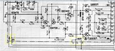
7500amp.jpg
 
You wrote "I powered the unit on using the DBT at 50W and no shorts but no click."
Does the 50W indicate you have a 50 watt bulb in the DBT? IMO that is too small it will create a large voltage drop.
Measure the AC voltage on one of the outlets on the amp to see what the incoming voltage is.

You also wrote "2. The DC offset adjustment (I think that's what it's called. Not labeled in the manual.) at pins 3 (left channel) and 17 (right channel) with - DMM test lead to ground yield craploads of DC voltages. ~15vdc. Seems like that little protection circuit is doing its thing."
Pins 13 and 17 where? I'm guessing you perhaps meant pins 3 and 17 of the amp board?

Confirm you have the correct voltages at the amp board.

View attachment 3478341
@mrk229 thanks! The 50 watt bulb is not at full glow. I do have a 75 and 100. Should I switch to one of those? I'll measure the AC voltage in first.

Yes, pins 3 and 17 on the amp board. I'm pretty sure that's the DC offset adjust. That's way off, at the moment.

I'll measure the voltages going into the amp in a few and report back.
 
@mrk229 thanks! The 50 watt bulb is not at full glow. I do have a 75 and 100. Should I switch to one of those? I'll measure the AC voltage in first.

Yes, pins 3 and 17 on the amp board. I'm pretty sure that's the DC offset adjust. That's way off, at the moment.

I'll measure the voltages going into the amp in a few and report back.
If all is well or nothing is seriously wrong the bulb should just barely be glowing at idle with no audio present. Barely glowing will give a minimum voltage drop. The brighter the filament, the higher its resistance is and the higher the voltage drop.

I use a 100 watt bulb for most everything.
 
If all is well or nothing is seriously wrong the bulb should just barely be glowing at idle with no audio present. Barely glowing will give a minimum voltage drop. The brighter the filament, the higher its resistance is and the higher the voltage drop.

I use a 100 watt bulb for most everything.
I think I'm in the seriously wrong category. My voltages are pretty low on everything, even with the 100w bulb. It's also fairly bright. Not at full power but not dim. Maybe 30-40 percent bright.

Amp board pins:
P10: -8
P6: 17
P12: -16

One thing that was odd was these voltages started higher and continued to climb downward. They didn't start very high but P6 was near 20 and backed down to 17. It may even have gone lower.

Another clue: The ground seems like it has some current flowing to it. I noticed that when I was removing the positive grabber. Maybe something is shorted to ground?

Forgot to measure at mains. I'll do that soon. But save to say we know something is wrong and it's not the lack of current?
 
I think I'm in the seriously wrong category. My voltages are pretty low on everything, even with the 100w bulb. It's also fairly bright. Not at full power but not dim. Maybe 30-40 percent bright.

Amp board pins:
P10: -8
P6: 17
P12: -16

One thing that was odd was these voltages started higher and continued to climb downward. They didn't start very high but P6 was near 20 and backed down to 17. It may even have gone lower.

Another clue: The ground seems like it has some current flowing to it. I noticed that when I was removing the positive grabber. Maybe something is shorted to ground?

Forgot to measure at mains. I'll do that soon. But save to say we know something is wrong and it's not the lack of current?
That seems to point to a power supply problem. With the voltages coming into the amp board being that far off I would expect it to not be working as designed.

Pioneers are well know to run power supplies very hot and electronic components typically don't like lots of heat over time.

Some of the regulators (pass transistors) get so hot that the solder joints at the very least deteriorate and at the worst they desolder themselves.

Have a good look at all of the parts on the power supply section of the AWM-072 switch circuit board top and bottom.

Check the voltages on the AWM-072. Also check the fuses (FU 2 & 3) with a meter

7500ps.jpg
 
That seems to point to a power supply problem. With the voltages coming into the amp board being that far off I would expect it to not be working as designed.

Pioneers are well know to run power supplies very hot and electronic components typically don't like lots of heat over time.

Some of the regulators (pass transistors) get so hot that the solder joints at the very least deteriorate and at the worst they desolder themselves.

Have a good look at all of the parts on the power supply section of the AWM-072 switch circuit board top and bottom.

Check the voltages on the AWM-072. Also check the fuses (FU 2 & 3) with a meter

View attachment 3478394
Q1 BCE: 18, 18, 17
Q2: 7, 18, 12
Q3: -19, -19, -19
Q4: -6, -20, -9

All on DBT 100 watts. I didn't go any further because something already seems off.
 
Yes something does seem way off.

Did you confirm the fuses are good?

Check the AC voltage from pin 13 to pin 14, and pin 13 to ground and pin 14 to ground.
 
Yes something does seem way off.

Did you confirm the fuses are good?

Check the AC voltage from pin 13 to pin 14, and pin 13 to ground and pin 14 to ground.
Fuses all confirmed good.

13 to 14: ~40vac (starts at 47 and continues down, maybe normal?)
13 to ground: ~ half that
14 to ground ~ same

Seems like the rectifier diodes and C6, C11 are worth investigating? I do have spares for the diodes and maybe the caps.
 
Last edited:
You Wrote: "13 to 14: ~40vac (starts at 47 and continues down, maybe normal?)" Looks like DBT may be limiting with voltage drop trending up.

DBT bulb size?
AC voltage at amp AC socket while on DBT.
 
You Wrote: "13 to 14: ~40vac (starts at 47 and continues down, maybe normal?)" Looks like DBT may be limiting with voltage drop trending up.

DBT bulb size?
AC voltage at amp AC socket while on DBT.
What is the safest way to do this? - to the chassis and + to one of the wires going to the transformer?
 
What is the safest way to do this? - to the chassis and + to one of the wires going to the transformer
Again DBT bulb size you are using?

Measure the voltage directly at the switched AC outlet on the back of the amp. If it is hard to get to the connections safely you standard meter probes should slip into the socket.
This will tell us if the bulb is limiting the voltage too much.

And it may tell us why "13 to 14: ~40vac (starts at 47 and continues down, maybe normal?)"
 
Again DBT bulb size you are using?

Measure the voltage directly at the switched AC outlet on the back of the amp. If it is hard to get to the connections safely you standard meter probes should slip into the socket.
This will tell us if the bulb is limiting the voltage too much.

And it may tell us why "13 to 14: ~40vac (starts at 47 and continues down, maybe normal?)"
100 watt DBT. So + goes into one end of the spare AC plugs on the back and - goes into the other? Doesn't matter which goes where because it's not polarized?
 
Back
Top Bottom