• Please note that Audiokarma will be offline briefly for updates early on Monday morning, September 28th.

Pioneer SA-8100 Power Supply Issue? - Help!

forsgren

AK Subscriber
Subscriber
Don't you hate it when things are going great, and then you screw up? I am in the process of restoring my beloved SA-8100. So far, I have rebuilt the Power Supply board (AWR-030), all new caps, transistors, Zener diode. Same with the Protection board (AWM-027) and Filter Amp board (AWK-020). The next board was the Power Amp Board (AWH-022). To gain access to the back of the amp board, one must move the Protection board, I had replaced all of the capacitors and had started on the 2SC1451 transistors (replaced with KSC3503), After transistor replacement, I powered the unit on to make sure the orientation was correct, I then proceeded to the other 2SC1451. I had the Protection board held out of the way and on this particular time, forgot to move it out of the way. Immediately after turning it on, the amp went dead and it went into protection. It shorted on the Filter Amp board, I cannot tell exactly what pins touched what. Initaially


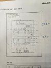
You can see the voltages, they are strange. Pin 3 should read +50v, I get a few millivolts, I know the transformer is working as I am getting 40v AC on Pins 7 and 8. The other strange thing is that Pins 12, 13, 14 and 15 are roughly 1/2 of the correct voltage. I did check the Zener, all 4 transistors, and Diodes 5-8, they all test good.
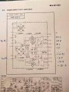
SA-8100 Power Supply edit.jpg

The Power Amp board looks correct.

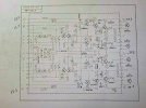
SA-8100 Ampliier edit.jpg

As does the Protection Board

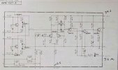
SA-8100 Protection edit.jpg

Initially, I thought the main output transistors were the culprit, using a meter, I tested a dead short on Q16, the 2SD370, in order to test out of circuit, I had to remove the entire Power Amplifier Board. Once removed, the transistors were all good, I cleaned them and reinstalled using Silpads. I was extremely careful upon reinstalling the board. All connections are correct and there are no shorts. I got the same results as before, The unit goes into protection.

Has anyone had a similar experience? This makes me sick. Any ideas please chime in! Thank you!
 
Register to hide this ad
:( I think in one way or another we have all been there. Have you closely inspected the bottom of the board?
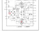
Since it looks like the positive side of the regulated supply is working I think you may have blown the trace on the pc board that leads to what you are calling pin three 3.
I think what you are calling pin three is actually pin 9?

(edited after reading the OP again I not think the trace is blown, see post #4)
 
Last edited:
You did not mention if any of the fuses were blown after the incident?
Are you using a dim bulb tester?

After reading your original post again It actually appears that the +50 is working as it shows up on the amplifier board +B1. (pins 5 & 21)

It looks like the negative supply is possibly the root of your problem, it certainly has issues. @petehall347 raises a good point. look for broken ground wires caused by moving the boards around.

Check the voltage at the minus side of C7 it should be in the neighborhood of -50V.
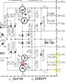
Check the voltage at the point noted in the below image (base of Q2).
If it is low check the values of R2, R4 & R6.

SA-8100 Power Supply edit.jpg
 
You may have a short in one of the other boards that uses the PS feeds.
The low readings on the PS is the abnormal draw from one of those boards.
If you can do a voltage drop on each of the resistors R14, R16? See which one is drawing a high current. Or remove the wire from the board at a point where its easy. Like remove the entire pin, wire wrap and all.
See if the voltage comes back. Focus on that ancillary circuit.
That kind of draw would be seen on the DBT. It would require some experience knowing the DBT lamp wattage and what is considered normal with that unit.
 
You may have a short in one of the other boards that uses the PS feeds.
The low readings on the PS is the abnormal draw from one of those boards.
If you can do a voltage drop on each of the resistors R14, R16? See which one is drawing a high current. Or remove the wire from the board at a point where its easy. Like remove the entire pin, wire wrap and all.
See if the voltage comes back. Focus on that ancillary circuit.
That kind of draw would be seen on the DBT. It would require some experience knowing the DBT lamp wattage and what is considered normal with that unit.

If the - 18 or -14 volt rail was drawing down the -42 raw supply voltage to -21 as noted by the OP at pin 12 I would think that R2 would fail.
 
Maybe:
DBT in use?
Its a 1/2 watt resistor.
?
Pin 15 is reading close to the -13 so the zener is good.
Probably check the resistors in that Negative pass regulator circuit. Definitely a good idea.
After 18 years of tinkering on these receivers I still go to a physical mode of TS if I find it easer. I'm thinking of the OP and a experience level.
 
First off, thank you all for jumping in!

The unit is not hooked up to a DBT, when the event occurred, none of the fuses were blown.

The negative side of C7 reads 52.7v, the base of Q2 reads 21.6v, the collector reads 51.9v and the emitter reads 21.0v.

I removed one leg of R2, R4 and R6:
R2 - 24.4 ohms
R4 - 1.52k ohms
R6 - 1.52k ohms

Pin 2 on the protection board reads 19.58v, Pin 4 15.2v.

Here is the Filter Amp board, this is what the protection board shorted against.

SA-8100 Filter Amp.jpg

The voltages are similar to the PS where they come from.

I have looked around again, I see no shorts, or open solder traces/bridges.
 
First off, thank you all for jumping in!

The unit is not hooked up to a DBT, when the event occurred, none of the fuses were blown.

The negative side of C7 reads 52.7v, the base of Q2 reads 21.6v, the collector reads 51.9v and the emitter reads 21.0v.
Did you have the red meter lead on C7? Those voltages should all be negative with respect to ground. Where was your negative lead?


I removed one leg of R2, R4 and R6:
R2 - 24.4 ohms
R4 - 1.52k ohms
R6 - 1.52k ohms

Pin 2 on the protection board reads 19.58v, Pin 4 15.2v.

Here is the Filter Amp board, this is what the protection board shorted against.


The voltages are similar to the PS where they come from.

I have looked around again, I see no shorts, or open solder traces/bridges.
OK we know the resistors are good, and I think we know the raw power supply (negative side of C7) is good.

As @zebulon posted earlier:
"You may have a short in one of the other boards that uses the PS feeds.
The low readings on the PS is the abnormal draw from one of those boards.
If you can do a voltage drop on each of the resistors R14, R16? See which one is drawing a high current."


Forgive me as I don't know your skill level. To measure voltage drop across the resistors you place one meter lead on one end and the second meter lead on the other end.
For fun and since it is quick, measure the voltage drops across R14 and R16.

In this case you can quickly perform check with the terminals on the board.
One meter lead stays on pin 12.
Other meter lead to pin 13 to read the drop across R14
Move meter lead to pin 14 to read the drop across R16

SA-8100 Power Supply edit1.jpg
With the voltage drops you can calculate the actual current flow through the resistor. Or we can work it with the information we already have.
Lets see how close we get.

We know the voltage at pin 12 is 21.5 volts. That voltage is on one end of both R14 and R16.

R14 has 21.5 volts on one end and 10.5 (rounding for easy math) on the other end. That leaves 11 volts across R14.
R16 has the same 21.5 volts on one end and again rounding 6.5 on the other end. That 15 volts across R16.

Since the filter amp was involved try unsoldering and lifting pin 8 and see if the voltages on the power supply pins return to normal.
 
mrk229, thanks again, I have been doing this for many years, and have gone through well over 100 pieces, not perfect (obviously), and do make the occasional mistake.

I failed to list the negative side of C7 as a negative voltage, it is -52.7v.
The voltage drop from Pin 12 to 13 yields -10.62v, Pin 12 to 14 yields -14.78v

I did remove the lead from Pin 8 on the filter amp board, the unconnected wire read 12.4v, when hooked up again, it read 6.18v.
While disconnected Pin 15 read -12.46v (the same as before), Pin 14 read -12.48v (before it was -6.4v), Pin 13 read the same -10.44v.
 
Thanks for the update on your skills. Makes it a little easier going forward.

The measured data is close to the calculated data and we can us it figure out some current draws.
The current draw through R14 8.8mA
The current draw through R16 11.37mA

Those don't seem out of whack to me, they are about half of the specified idle draw from the schematic.
And since the supply voltage is about 50% of normal then double the voltages and double the currents for normal operation.

I am leaning towards Q2. Do you have a way to test the HFE of Q2 or a suitable transistor to swap in there?
 
Thank you. Using the Atlas DCA55, the HFE on the original 2SB507 is 92, and the replacement KSC3503 is 113. I did for the fun of it, swap the old one back in, unfortunately, I got the same result. I keep going back to when I replaced the first transistor on the Power Amp board, I made sure it worked and then I proceeded to replace another and I shorted out the Filter Amp board. Something was affected, I just cannot put my finger on it.

Again, I really appreciate the help. We are going out of town for the rest of the week, hopefully, I can think about this and find a solution!
 
Thank you. Using the Atlas DCA55, the HFE on the original 2SB507 is 92, and the replacement KSC3503 is 113. I did for the fun of it, swap the old one back in, unfortunately, I got the same result. I keep going back to when I replaced the first transistor on the Power Amp board, I made sure it worked and then I proceeded to replace another and I shorted out the Filter Amp board. Something was affected, I just cannot put my finger on it.

Again, I really appreciate the help. We are going out of town for the rest of the week, hopefully, I can think about this and find a solution!

Have you checked the voltages around Q4? Also since you have a DCA55 you could test Q4, and perhaps check R10 & R12.

It's something simple we are missing.

Pretty sure it is related to the base voltage of Q2.
 
q2 base will be at -22v . or damn close .
Yes agreed, he measured -21.6 before.

Q2 base is supposed to be -42.6 and I can't quite wrap my head around what might be pulling it down.

Collector voltage is -51.9 which is what I would expect to see for the input voltage for this circuit.

With the base voltage at -21.6 the emitter is at -21 as you might expect, so it seems Q2 is behaving normally.

What is causing the low base voltage?
 
OK, nice break and I am back at it.

I wondered what could have been affected when I touched the Filter Amp Board. I checked the transistors on the Filter Amp board and Q1 was dead. I replaced it with another KSC1845. Protection mode remained on.

@petehall347, the earth ground is correct, the amplifier worked perfectly before and I highly doubt this is an issue.

I checked the voltages at Q4, remember that I did swap out the 2SA733 for a KSA992 and the voltages are as follows:
E -12.36v
B -11.88v
C -21.57v

I then put the original 2SA733 and got these voltages:
E -12.5v
B -11.9v
C -40.14v

R10 measures 29.19 ohm (30K) ohm, R12 measures 14.98k and is a (15k) resistor.

The voltage on C11 is -45.3v on one side and 0v on the other.

I measured Q2 again and got the following voltages:
E -39.47v
B -40.11v
C -50.52v

The good news is that now the voltages at pins 12, 13, 14 and 15 seem to be close:

12 -39.5v
13 -22.5
14 -16.4v
15 -12.1v

The unit still stays in protection mode. Thanks for the follow-up!
 
Back
Top Bottom