• Please note that Audiokarma will be offline briefly for updates early on Monday morning, September 28th.

Pioneer SA-8100 Power Supply Issue? - Help!

The voltages on the Protection Unit (AWM-027-A) are similar as before:

Pin 6 -12.39v
Pin 16 34.49v
Pin 17 7.5v AC
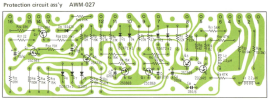
 
Here is a wrench in the works. I have the AWM-027-D version, the following is the "D" version. I cannot locate a schematic diagram for this.
1725428474377.png

This is what we have been working on, I don't know if they are the same board or if they are interchangeable?
1725428579450.png

Here are the other voltages, obviously something is not right.

Pin 6 -12.39v
Pin 16 34.49v
Pin 17 7.5v AC
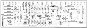
Pin 14 34.57v (it shows 8v on the schematic but is it the correct voltage for the "D" version). At any rate, the voltages on Q7 are not close, I do see 0.7v at the base fo Q6. I pulled Q7 (sSC1384 and it checked good, I tried replacing it with the KSC2690 and got the same voltages).

At the base of Q5 I get 6.09v, which should be 20.6v.

We are chasing our tails until we can verify if the boards are compatible. I think the Diodes 5,6 and 7 are part of the issue, if you look at the "D" board, these were very close to the pins that shorted out.
 
Here is a wrench in the works. I have the AWM-027-D version, the following is the "D" version. I cannot locate a schematic diagram for this.
View attachment 3289403

This is what we have been working on, I don't know if they are the same board or if they are interchangeable?
View attachment 3289404

Here are the other voltages, obviously something is not right.

Pin 6 -12.39v
Pin 16 34.49v
Pin 17 7.5v AC

Pin 14 34.57v (it shows 8v on the schematic but is it the correct voltage for the "D" version). At any rate, the voltages on Q7 are not close, I do see 0.7v at the base fo Q6. I pulled Q7 (sSC1384 and it checked good, I tried replacing it with the KSC2690 and got the same voltages).

At the base of Q5 I get 6.09v, which should be 20.6v.

We are chasing our tails until we can verify if the boards are compatible. I think the Diodes 5,6 and 7 are part of the issue, if you look at the "D" board, these were very close to the pins that shorted out.
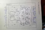
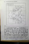
Schematic for AWM-027 Does not give a revision number.

awm-027.jpg
 
We are chasing our tails until we can verify if the boards are compatible. I think the Diodes 5,6 and 7 are part of the issue, if you look at the "D" board, these were very close to the pins that shorted out.
The diodes are the steering controls for the fault detection circuits to trigger the protection mode via Q5.
The voltages shown on the schematic are for the circuit in the normal operation (relay on) of the circuit. IE not in protection.

What are the voltages at pins 2 and 4?
 
Good evening, here are the fresh voltages, from the top left side:

Pin 9 -29.86v
Pin 10 -29.86v
Pin 12 18.16v
Pin 11 17.16v
Pin 1 -27.98v
Pin 3 17.16v
Pin 2 -29.97v
Pin 4 17-17v
Pin 6 -12.48v
Pin 17 7.5v AC
Pin 7 ground
Pin 14 24.57v
Pin 15 34.63v
Pin 16 34.49v

Thank you.
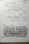
 
Good evening, here are the fresh voltages, from the top left side:

Pin 9 -29.86v
Pin 10 -29.86v
Pin 12 18.16v
Pin 11 17.16v
Pin 1 -27.98v
Pin 3 17.16v
Pin 2 -29.97v
Pin 4 17-17v
Pin 6 -12.48v
Pin 17 7.5v AC
Pin 7 ground
Pin 14 24.57v
Pin 15 34.63v
Pin 16 34.49v

Thank you.
both amps have problems , first check all the output transistors
then get all driver board pin voltages including the ones that are ground .
 
Last edited:
Well, the trip turned out a little longer than anticipated. I have been busy with a few other things as well.

Looking at the Control Amp Board (AWG-071) nothing looked suspicious

.SA-8100 Control Amp 1005.jpg

Same with the Equalizer Amp (AWF_006-01).

SA-8100 Equalizerl Amp 1005.jpg

However, the Power Amp Board (AWH-022-A) is really interesting. The output transistors on one channel are 16.6 - 17.06 volts, their corresponding pair are 31.2 - 39.3 volts which is normal. I measured the emitter resistors and did get an unstable reading on the resistor closest to Q18, it did stabilize after a few. I suspect that one or both of these transistors are bad and were affected when things got shorted out. However, before I remove the entire amplifier section to get to these, could there be other possible culprits?

SA-8100 Power Supply 1005.jpg

Thank you!
 
Well, the trip turned out a little longer than anticipated. I have been busy with a few other things as well.

Looking at the Control Amp Board (AWG-071) nothing looked suspicious

.View attachment 3313188

Same with the Equalizer Amp (AWF_006-01).

View attachment 3313189

However, the Power Amp Board (AWH-022-A) is really interesting. The output transistors on one channel are 16.6 - 17.06 volts, their corresponding pair are 31.2 - 39.3 volts which is normal. I measured the emitter resistors and did get an unstable reading on the resistor closest to Q18, it did stabilize after a few. I suspect that one or both of these transistors are bad and were affected when things got shorted out. However, before I remove the entire amplifier section to get to these, could there be other possible culprits?

View attachment 3313192

Thank you!
Are you sure about the reading at pin 14? That should be at ground potential. Ohm check it to the chassis.

Also pin 8 should not have any voltage on it.
 
Out of town again. I rechecked pin 14, it does indeed have -34.43 volts present. Piin 8 has zero. When I checked for resistance between pin 14 and ground, there is none.
 
Pin 4, 8, 9, 14, 17, 18 and 22 are all supposed to be going to ground. 8 & 9 and 17 & 18 are connected together on the PCB.

You need to follow those wires back to wherever they are going. Some of them are most likely going to a multiground terminal screwed to the chassis. if nothing is obviously broken off of hanging in mid-air then ohm check the wires.

8100pa.jpg

8100ps2.jpg
 
Back
Top Bottom