


You are using an out of date browser. It may not display this or other websites correctly.
You should upgrade or use an alternative browser.
You should upgrade or use an alternative browser.
Pioneer SA-8100 protection issue
- Thread starter Philsound
- Start date
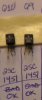

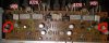
in the picture there are three LARGE components in a row on BOTH the left and right sides of the board.
A black heat sink with transistor
a funny looking silvery thing
a gray electrolytic cap
The "funny looking silvery thing" with the c-shaped chunk of metal sticking up? THAT'S the 2sc1451.
A black heat sink with transistor
a funny looking silvery thing
a gray electrolytic cap
The "funny looking silvery thing" with the c-shaped chunk of metal sticking up? THAT'S the 2sc1451.

Really. OK, thanks for that.
So the SM I have, at least for the PA board, is just slightly different, I let that confuse me. That also explains the values of R53 & R54 being listed as 1.5K when on my board they are 15K.
I guess I'll be looking for the correct document for the "B" version of this board.
Thanks Mark and Larry.
So the SM I have, at least for the PA board, is just slightly different, I let that confuse me. That also explains the values of R53 & R54 being listed as 1.5K when on my board they are 15K.
I guess I'll be looking for the correct document for the "B" version of this board.
Thanks Mark and Larry.
R53 and R54 are input filters in the power line.
edit - reverse engineering PROVES they are SUPPOSED TO BE 15000 OHMS....
R53 = R54 = 15k = 15000 ohms, impossible. The picture is inconclusive - I can't even tell if they are burned, no less reads the color codes.
Need a close up in good light to even start to try to figure it out.
3 digit color code
Brown green red gold is 1.5k = 1500
brown green orange gold is 15k = 15000
4 digit color code
brown green black brown gold = 1500
brown green black red gold = 15000
There are other manuals out there that show the correct transistor orientation.
The 90 meg service manual is a -a board, but the 4 meg "schematic" sa-8100s.pdf has the correct board layout for you.
edit - reverse engineering PROVES they are SUPPOSED TO BE 15000 OHMS....
R53 = R54 = 15k = 15000 ohms, impossible. The picture is inconclusive - I can't even tell if they are burned, no less reads the color codes.
Need a close up in good light to even start to try to figure it out.
3 digit color code
Brown green red gold is 1.5k = 1500
brown green orange gold is 15k = 15000
4 digit color code
brown green black brown gold = 1500
brown green black red gold = 15000
There are other manuals out there that show the correct transistor orientation.
The 90 meg service manual is a -a board, but the 4 meg "schematic" sa-8100s.pdf has the correct board layout for you.
Last edited:
R53 and R54 are input filters in the power line.
R53 = R54 = 15k = 15000 ohms, impossible. The picture is inconclusive - I can't even tell if they are burned, no less reads the color codes.
Need a close up in good light to even start to try to figure it out.
3 digit color code
Brown green red gold is 1.5k = 1500
brown green orange gold is 15k = 15000
4 digit color code
brown green black brown gold = 1500
brown green black red gold = 15000
There are other manuals out there that show the correct transistor orientation.
The 90 meg service manual is a -a board, but the 4 meg "schematic" sa-8100s.pdf has the correct board layout for you.
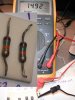
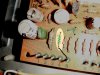
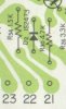
Take a look at these pics - both resistors are reading close to 15K (I said one was open - I was wrong!).
Definately Brn, Grn, Org, Gold. Definately 15K. Definately R53 & 54.
Hope you don't mind me being slow, time-wise. It's that whole busy lifestyle thing.
I'll go find that other PDF with the schematic for the 022B board.:thmbsp:
Attachments

I have looked at that very closely, reverse engineered the thing.
It IS set up for 15000 ohms. Only that stage is powered by those resistors, drawing less than a milliamp.
So the schematic is in error. What you have found is correct, from a reverse engineering standpoint, as opposed to the numbers just copied by a draftsman.
It IS set up for 15000 ohms. Only that stage is powered by those resistors, drawing less than a milliamp.
So the schematic is in error. What you have found is correct, from a reverse engineering standpoint, as opposed to the numbers just copied by a draftsman.
I have looked at that very closely, reverse engineered the thing.
It IS set up for 15000 ohms. Only that stage is powered by those resistors, drawing less than a milliamp.
So the schematic is in error. What you have found is correct, from a reverse engineering standpoint, as opposed to the numbers just copied by a draftsman.
Reverse Engineered - you are amazing.
I've finished replacing the transistors on this 022 board. I haven't done anything else, forgot to order the adjustable pots, I'll get those next week.
I'm not really in any hurry (and in fact, felt lucky to get most of this morning to work on it) but do you think I should DBT it now and see if it comes out of protection? Oh, I have asked for some critique of my soldering in another thread and will fix problems there before DBT.
Or should I wait for the pots?
Or is there anything else you'd like to see done before DBT?
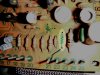
Repair bench picture for grins.
Attachments

I have looked at that very closely, reverse engineered the thing.
It IS set up for 15000 ohms. Only that stage is powered by those resistors, drawing less than a milliamp.
So the schematic is in error. What you have found is correct, from a reverse engineering standpoint, as opposed to the numbers just copied by a draftsman.
"as opposed to numbers copied by a draftsman" - this reminds me - did you say at one point that we should orient new xsistors by checking ECB orientation on the original and not by the markings on the board??? 'Cause that's what I did, I went by the symbols on the board. Crap, do I need to go back and check them all via the schematic\pre-pictures?
The level of care and checking for pcb silk screening and the service manual's schematic is very different. Verification would be to identify other components sharing a transistor lead's foil.
Unless there is a problem, I wouldn't unless I had time to kill/fill.
Wait for the trim pots. Old pots can mess up all your work if they go open circuit. The only un corroded spot on the commutator ring for the center tap is where the old adjustment contacted it.
Unless there is a problem, I wouldn't unless I had time to kill/fill.
Wait for the trim pots. Old pots can mess up all your work if they go open circuit. The only un corroded spot on the commutator ring for the center tap is where the old adjustment contacted it.
Whew,
Not familiar with the trimmers - will any just work?
I've read thru posts here and the Bournes are favored, but Mouser only has one 10K and it's at least 2 months out.
I've found one (not a Bourne) at Jameco, and I could get it by next week.
These are VR1 and VR2 "semi-fixed(10K-B) Part No. C92-049-0" as listed in SM.
Any guidance would be appreciated.
Not familiar with the trimmers - will any just work?
I've read thru posts here and the Bournes are favored, but Mouser only has one 10K and it's at least 2 months out.
I've found one (not a Bourne) at Jameco, and I could get it by next week.
These are VR1 and VR2 "semi-fixed(10K-B) Part No. C92-049-0" as listed in SM.
Any guidance would be appreciated.
OK,
I got my search terms fixed and found a variety of 10K trimmers.
Can anyone point to one that would be preferred over others? I'm not even sure how to define the size\pin arrangement.
Here's where you can see what's available
TIA
I got my search terms fixed and found a variety of 10K trimmers.
Can anyone point to one that would be preferred over others? I'm not even sure how to define the size\pin arrangement.
Here's where you can see what's available
TIA
Ha, I'm a glutton for punishment.
I've got all the pieces replaced that you said, Mark.
Put it back together, powered up on Dimbulb, and unit no longer goes into protection.
I set idle and neutral adjustment, which came out spot on.
Tested with input and speakers and the left output works great - right output doesn't work at all. Can barely hear the output, and of course, sounds distorted. Checked my solder work (marginal), orientation of transistors that I replaced, no problems seen. I also checked with multiple inputs, and "toggled" all the controls, none had an effect, right channel output very very low & distorted.
Jumped that channel on the relay, no change, right channel still not working. But a clue maybe - while relay is jumped, when powering up, the right channel sounds fine BEFORE the relay closes. Once the relay closes, the sound is gone. Same on power down, relay opens and right channel sounds fine for the few seconds that the unit is still powering down.
Mark, what would you like for me to do, if you are still willing\able to help? Anyone else can jump in, Mark is busy and probably would appreciate the help.
I've got all the pieces replaced that you said, Mark.
Put it back together, powered up on Dimbulb, and unit no longer goes into protection.
I set idle and neutral adjustment, which came out spot on.
Tested with input and speakers and the left output works great - right output doesn't work at all. Can barely hear the output, and of course, sounds distorted. Checked my solder work (marginal), orientation of transistors that I replaced, no problems seen. I also checked with multiple inputs, and "toggled" all the controls, none had an effect, right channel output very very low & distorted.
Jumped that channel on the relay, no change, right channel still not working. But a clue maybe - while relay is jumped, when powering up, the right channel sounds fine BEFORE the relay closes. Once the relay closes, the sound is gone. Same on power down, relay opens and right channel sounds fine for the few seconds that the unit is still powering down.
Mark, what would you like for me to do, if you are still willing\able to help? Anyone else can jump in, Mark is busy and probably would appreciate the help.
If the left channel works and the right does not, then use the DMM and compare all the bjt bias points (ebc) against each other. The most important ones are written on the schematic, others you add to your printed schematic copy or write them down so you can post for the forum members to review. It is a matter of trail and error, method of comparison.
Another method is: With the unit powered off, you can also do a nodal comparison using the ohmmeter and compare good vs bad. That is the beauty of having two channels.
Load isolation relay contact jumping is not a good idea unless you are using a big 4-16 ohm load resistor to replace a speaker load which is usually what I would use. Only hook up speakers after you have thoroughly tested out the PA/protection sections and are assured that they are functioning properly. Jumping the isolation relay can weed of bad contacts causing distortion. The feedback loop is before the relay.
Good luck
Rick
Another method is: With the unit powered off, you can also do a nodal comparison using the ohmmeter and compare good vs bad. That is the beauty of having two channels.
Load isolation relay contact jumping is not a good idea unless you are using a big 4-16 ohm load resistor to replace a speaker load which is usually what I would use. Only hook up speakers after you have thoroughly tested out the PA/protection sections and are assured that they are functioning properly. Jumping the isolation relay can weed of bad contacts causing distortion. The feedback loop is before the relay.
Good luck
Rick
Last edited:
If the left channel works and the right does not, then use the DMM and compare all the bjt bias points (ebc) against each other. The most important ones are written on the schematic, others you add to your printed schematic copy or write them down so you can post for the forum members to review. It is a matter of trail and error, method of comparison.
Another method is: With the unit powered off, you can also do a nodal comparison using the ohmmeter and compare good vs bad. That is the beauty of having two channels.
Load isolation relay contact jumping is not a good idea unless you are using a big 4-16 ohm load resistor to replace a speaker load which is usually what I would use. Only hook up speakers after you have thoroughly tested out the PA/protection sections and are assured that they are functioning properly. Jumping the isolation relay can weed of bad contacts causing distortion. The feedback loop is before the relay.
Good luck
Rick
Thanks Rick, that's a good idea - the comparison. I am familiar with the theory of comparison - I have an off-road truck, highly modified. I have the another truck, exactly the same as the first except this one has virtually no mods. The second truck is strictly for reference, I only drive it enough to keep things lubed.
Ah-ha! Successful repair.
Amp side tested fine (via rear panel in\out). So focused on the pre-amp side, traced voltages thru and found Control Amp board 017B not working properly.
Started going thru the board, replacing and testing, one component at a time. Naturally, I started at the wrong end of the channel and had most of the components replaced before I got to the other end of the channel.
So, finally:
Found C1 bad, replaced it - still not working.
Found C11 bad, replaced it - Success!
The channel does now have all new transistors and new caps (except those really small ones).
The other channel is untouched, all original.
Idle and Neutral adjustments are spot on.
Unit sounds good so far! All the controls are smooth (they better be, after the meticulous cleaning and lube they got) and the relay doesn't seem to be causing any issues (I cleaned it rather than replace).
Thanks for the support and I'm sure I'll be back asking for help again sometime.:thmbsp:
Amp side tested fine (via rear panel in\out). So focused on the pre-amp side, traced voltages thru and found Control Amp board 017B not working properly.
Started going thru the board, replacing and testing, one component at a time. Naturally, I started at the wrong end of the channel and had most of the components replaced before I got to the other end of the channel.
So, finally:
Found C1 bad, replaced it - still not working.
Found C11 bad, replaced it - Success!
The channel does now have all new transistors and new caps (except those really small ones).
The other channel is untouched, all original.
Idle and Neutral adjustments are spot on.
Unit sounds good so far! All the controls are smooth (they better be, after the meticulous cleaning and lube they got) and the relay doesn't seem to be causing any issues (I cleaned it rather than replace).
Thanks for the support and I'm sure I'll be back asking for help again sometime.:thmbsp:
Disappointed!
After letting the unit play for about an hour, I shut it down. Unplugged the unit.
I let it set for about 10 minutes - not long enough. Started putting boards back, and went to put one of the metal shields back in.
Spark! The shield grounded on the large output heat sink and also touched the back of the protection board.
Now, nothing out of the pre-amp side. I cannot tell you how bummed I am about it.
Questions:
Obviously, a cap was still charged.
1) Do you guys discharge all the caps before re-assembly? Or just the large ones? Or somehow make sure the metal shields don't touch things in the re-install?
2) Any guesses on what I blew up? Hopefully just something on protection board AWG-027. I haven't even started checking voltages, too bummed about the whole thing. Caps or transistors most likely? Diode?
Damn damn damn.
After letting the unit play for about an hour, I shut it down. Unplugged the unit.
I let it set for about 10 minutes - not long enough. Started putting boards back, and went to put one of the metal shields back in.
Spark! The shield grounded on the large output heat sink and also touched the back of the protection board.
Now, nothing out of the pre-amp side. I cannot tell you how bummed I am about it.
Questions:
Obviously, a cap was still charged.
1) Do you guys discharge all the caps before re-assembly? Or just the large ones? Or somehow make sure the metal shields don't touch things in the re-install?
2) Any guesses on what I blew up? Hopefully just something on protection board AWG-027. I haven't even started checking voltages, too bummed about the whole thing. Caps or transistors most likely? Diode?
Damn damn damn.
Last edited:
I think the damage was to the power supply board. But I'm not sure.
If I separate the amp\pre with the switch on the back, the amp works fine, output is good.
When pre\amp are coupled, no output on either channel.
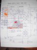
Here's a pic of where I think the problem is on the 030 board - I want to replace Q2 and Q4, is that right?
I have a crazy high-res version of that image, if you can't see what you need to see. for example, the base of Q4 should be at -13.6 but reads -0.6.
If I separate the amp\pre with the switch on the back, the amp works fine, output is good.
When pre\amp are coupled, no output on either channel.
Here's a pic of where I think the problem is on the 030 board - I want to replace Q2 and Q4, is that right?
I have a crazy high-res version of that image, if you can't see what you need to see. for example, the base of Q4 should be at -13.6 but reads -0.6.
Attachments
Last edited:
what is the emitter voltage of q4? 13v or 0v.
0v means zener is probably dead, or q4 is dead and not feeding the -13v zener.
I must inject some discipline to this free range thread.
post arm-030 voltages at pins 9,19,18,17,16,11,15,14,13,12,4 & 5
if pin 12 is not within 10 % of -42 volts, post voltage readings of q2 and q4.
0v means zener is probably dead, or q4 is dead and not feeding the -13v zener.
I must inject some discipline to this free range thread.
post arm-030 voltages at pins 9,19,18,17,16,11,15,14,13,12,4 & 5
if pin 12 is not within 10 % of -42 volts, post voltage readings of q2 and q4.