what is the emitter voltage of q4? 13v or 0v.
0v means zener is probably dead, or q4 is dead and not feeding the -13v zener.
I must inject some discipline to this free range thread.
post arm-030 voltages at pins 9,19,18,17,16,11,15,14,13,12,4 & 5
if pin 12 is not within 10 % of -42 volts, post voltage readings of q2 and q4.
Thanks for showing up, I was beginning to think I was on my own. LOL, yes, free range is what you get with lack of direction.
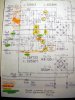
Possibly you didn't look at the picture (and I don't blame you, you may prefer just text numbers, easier to read) - but on that picture you can see that:
Q4 Emitter = 0 volts
Q4 Collector = -8.5
Q4 Base = -0.6
Q2 Emitter = -4.6 volts
Q2 Collector = -48.6
Q2 Base = -8.5
AWR-030: All measurements to ground
Pin 09: 48.9
Pin 19: 35.3
Pin 17: 29.0
Pin 16: 13.7
Pin 15: 0.0
Pin 14: 3.47
Pin 13: 6.93
Pin 12: -4.58
Pin 04: -36.8
Pin 05: 37.0
It's my opinion that Q4 is in need of replacement but that board is darn hard to get to the back, so that's why I've asked if you think I'm in the right spot.
Now, what I did expect from you Mark, was some significant chastisement for not draining the caps before re-assembly - which resulted in this damage! I have built "cap discharge" set of clips\resistor so that won't happen again. I *thought* the circuits had discharge circuits built in discharge - apparently not!
Last edited: