• The move to the new server is done. There are some software and database maintenance updates in process. This has us passing the hat around to help out. We appreciate any donations. Seriously, even a dollar helps. The payment page may be found here - https://www.audiokarma.org/support.html

Pioneer SA-900 hum

modernlover

New Member
I have a Pioneer SA-900 that I’ve been working on that developed a hum after the main filter caps had been replaced.

When that happened, I took out the new ones and tried the old ones again, but the hum persisted.

I had been following the thread as a guide for the current project.

i have checked all the ground connections and everything seems good.

Here is what I’ve been able to narrow down:
Hum is constant at zero volume on all inputs on both channels and is unaffected by volume knob.
The bass controls for both channels do affect the volume of the hum, but only when the knob is turned up, nothing happens when they are turned down.
The muting switch doesn’t lower the level of hum.
Nor does the pre/main decoupler.

However when the board is not screwed down, the muting switch does decrease the hum to inaudible as does decoupling the pre/main.

I can also reduce the hum when the screws that attach the power supply board to the chassis are loosened, but the muting switch can bring it right back.

i have looked over many of the forums regarding hum, and have tried many of them to no avail and much vexation. I’m hoping someone can point out there is something that I have overlooked, because this has become a frustrating obsession.
 
Register to hide this ad
If the only thing that changed from no hum to hum was you replacing the main filters, I'd have to imagine you changed the grounding scheme by accident. Unless was there anything else you did?
 
Right before that I had done the diodes and one transistor on the power supply. When I powered it up to test it, everything was working fine.

When I did the filter caps I kept the wiring connections the same just doing one leg at a time.
 
I redid the grounds for the filter caps, the power supply board, power light, headphone jack, and the transformer. Hum is still present.
 
Right before that I had done the diodes and one transistor on the power supply. When I powered it up to test it, everything was working fine.

When I did the filter caps I kept the wiring connections the same just doing one leg at a time.
Either way, if that’s what caused the hum, it’s something you did and we can’t know.
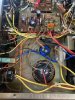
Pictures?
 
Did some more poking and prodding today. Seems the star ground idea wasn’t going to work. I did manage to make a difference in hum level though.

After wiggling the cluster of wires near that ground point I noticed a change in the volume of the hum. Turns out it was on the main amp ground that connected to that point. So for a quick test i undid the wire from the board and slotted in a new wire in a closer ground point and the hum significantly reduced.

It’s not completely gone but it’s at a much less annoying level. And I’ll do some more to see if different points make any difference.
 
No, do not modify the grounding scheme any more than you inadvertently did.

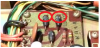
LOOK at the power supply board, two corners overlap the chassis threaded screw receptacles!!! Those are grounds, and are pretty important.
UN mount the power supply board, clean the foil at those corners, clean the metal of the chassis at those corners.
Then get some internal or external tooth star washers, stainless steel if possible, and put them between the board and the metal mounting tabs.
They are meant to facilitate contact, digging in slightly on both sides to form a very low resistance connection.
This is EXACTLY how a gas-tight connection is formed - like a wire wrap. The digging in part...
upload_2022-5-16_23-41-31.png

Also I do not like the appearance of the four capacitor solder joints nor the star ground. Looks like not enough heat, grainy and nubbly - did you have problems with them?

I could go on and on about the grounding in here, ESPECIALLY with the fact that the transformer is NOT centertapped and uses diodes to seek ground.
Basically there are AC currents flowing in the ground that across milliohms of resistance shows up as hum... IN a ground!!

So if your wiring of the capacitor's negative and grounds is EXACTLY as the factory wired it, this board's two grounds are at fault and causing AC current to snake around to reach it's destination. Net result... HUM.....

There is more I am digging into, but I sincerely hope that those star washers and corrosion free cleaned mounts fix the problem.

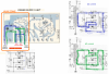
One thing to watch out for in the several pictures you referenced to check your wiring (why didn't you photograph it before changing anything out?) - it is a detail on the power supply board that may alter the grounding scheme. In one picture I see, there is a possible change in the foil by the D2 & D4 anodes.


upload_2022-5-17_0-14-34.png
 
Last edited:
Ideally the negative (ground) wire of the 2200uF 100v cap should be connected right in between the D2 & D4 anodes.
edit: instead of at the pins at the edge of the board.

This keeps the AC current as close as possible to the diodes and transformer wires exit.

Because that AC current IS flowing through the ground, and affecting things in it's path.

upload_2022-5-17_1-36-55.png
 
Last edited:
No, do not modify the grounding scheme any more than you inadvertently did.

LOOK at the power supply board, two corners overlap the chassis threaded screw receptacles!!! Those are grounds, and are pretty important.
UN mount the power supply board, clean the foil at those corners, clean the metal of the chassis at those corners.
Then get some internal or external tooth star washers, stainless steel if possible, and put them between the board and the metal mounting tabs.
They are meant to facilitate contact, digging in slightly on both sides to form a very low resistance connection.
This is EXACTLY how a gas-tight connection is formed - like a wire wrap. The digging in part...
View attachment 2568895

Also I do not like the appearance of the four capacitor solder joints nor the star ground. Looks like not enough heat, grainy and nubbly - did you have problems with them?

I could go on and on about the grounding in here, ESPECIALLY with the fact that the transformer is NOT centertapped and uses diodes to seek ground.
Basically there are AC currents flowing in the ground that across milliohms of resistance shows up as hum... IN a ground!!

So if your wiring of the capacitor's negative and grounds is EXACTLY as the factory wired it, this board's two grounds are at fault and causing AC current to snake around to reach it's destination. Net result... HUM.....

There is more I am digging into, but I sincerely hope that those star washers and corrosion free cleaned mounts fix the problem.

One thing to watch out for in the several pictures you referenced to check your wiring (why didn't you photograph it before changing anything out?) - it is a detail on the power supply board that may alter the grounding scheme. In one picture I see, there is a possible change in the foil by the D2 & D4 anodes.


View attachment 2568898

Mark, I am happy to see you. This is exactly the kind of advice I was looking for.

The grounds on the corners of the board were something I was aware of, and those were one thing I had been thinking about. However, there is only one corner that has exposed foil to attach to the mounting point.

I know that there are at least two versions of the board with slight differences, mostly on the ground path, extra pin near one of the capacitors. And I have only been able to find one other example of one like mine.

But I have not been able to find any pictures to reference of the underside of the board.

I will take your advice and order some star washers and do some cleaning of the ground point.
 
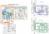
taking this to it's ultimate conclusion, moving the plus capacitor connection from the edge of the board, to a connection point between the diodes in the middle of the trace
minimizes the hum area, keeping the hum contained. segregated from the other current paths.

upload_2022-5-21_18-17-29.png
 
Last edited:
I reverted the ground I had moved back to where it originally came from. I cleaned and added star washers to the pad. I also took the face plate off and tightened all the controls to the chassis and tightened the faceplate, as I noticed that pushing on it made a difference.

All these things combined to reduce the hum to a level I might be able to live with. On speakers it is near inaudible.

The note about moving the capacitor leads is something I’d try, but that is above my comfort level, so I will not be trying it.

So that’s where I’m at. I really do appreciate the help and advice.
 
I reverted the ground I had moved back to where it originally came from. I cleaned and added star washers to the pad. I also took the face plate off and tightened all the controls to the chassis and tightened the faceplate, as I noticed that pushing on it made a difference.

All these things combined to reduce the hum to a level I might be able to live with. On speakers it is near inaudible.

The note about moving the capacitor leads is something I’d try, but that is above my comfort level, so I will not be trying it.

So that’s where I’m at. I really do appreciate the help and advice.
 
Back
Top Bottom