• The move to the new server is done. There are some software and database maintenance updates in process. This has us passing the hat around to help out. We appreciate any donations. Seriously, even a dollar helps. The payment page may be found here - https://www.audiokarma.org/support.html

Pioneer SA-9800 buz/ hum. I just can't fix.

Hi,
This is my first post on AK.
I just bought a Pioneer SA-9800 that was supposed to be fully working. I've been looking for one for a while and thought I had a good one ready to fully restore by re-capping and replacing some of the known bad transistors.
On inspection it had a very odd modification which resulted in the sound being attenuated to approx 25% of what you would expect from a 100W amp and loss of the loudness function.
The PCB from the volume pot was removed, this board was bridged with resistors and the volume pot was connected between the output on pre amp board and the main amp board inputs.
The normal wire connections to the preamp out and main amp in RCA connectors were removed.
Very strange.
With this modification although the volume was very much attenuated, there was only a quiet, acceptable hum, but no loudness function (not connected).
I managed to speak to the tech who did this (contact details were on a supplied receipt)
He told me that this modification was done to attenuate the hum, against his better judgement as the previous owner just wanted the hum gone and didn't need the amp to be very loud.
I reverted everything back to how it should be, reconnecting the volume pot PCB, re-connecting the pre-amp out socket to the preamp output on the filter board and re-connecting the main amp input sockets to the main amp boards .
The hum /buzz is quite bad.
From the speaker outputs (links in place) measured with a scope, it's 32mV pk to pk at 100Hz. Both channels.
Interestingly there is a 250 mV DC offset. (not present with the strange modification)
From the preamp output there is a 5mV pk to Pk (1mV RMS) 100z signal with no offset.
The hum is the same when I connect a source to the main amp in connectors at the rear of the amp.
The power supply board has been very recently re capped I am informed and this is obvious looking at the board.
I've checked for poor grounds, loose leads, obviously bad components, and broken bridged PCB tracks, etc.
The main filter caps appear to be in fairly good health with satisfactory capacitance and low ESR.
I have not checked if the hum is present/ same when connecting pre-amp out to another amps main in yet, but will try this when I dig out a suitable amp.
I'm really stumped.
This amp really should be restored to its original glory.
Are there any Pioneer experts out there who may have come across this problem
Any help would be really appreciated.
 
Register to hide this ad
Both speakers I take it.
Does the volume effect it?
I missed if you tried the pre amp separately.
 
Both speakers I take it.
Does the volume effect it?
I missed if you tried the pre amp separately.
Hi Zebulon,
Yes both speakers the same. Volume no effect. The sound is more muddy than I would have expected also. Im just digging out another amp that has separate main/pre to check, but there was a small 109Hz signal from pre amp when I scoped it (5 mV pk to Pk both channels).
 
Both channels probably a power supply.
Rectifier assembly in the regulated PS board AWR-191 (D1 -D4)?
The distorted sound might be from one out of the four diodes causing a half wave condition?
Just a thought.
Its probably a 120Khz?
You can check for the AC component on those +-68v rails right at the diodes. A Fluke should read it.
Check the filters C2 and C3 for polarity.
 
Both speakers I take it.
Does the volume effect it?
I missed if you tried the pre amp separately.
Update
Just spoken to the original owner.
He tells me that originally the amp wouldn't come out of protection mode. He got his tech to repair this, which he did, but that's when the hum started. He sent the amp back to him which resulted in the strange modification that I have posted about. It fixed the hum but left the amp in a sick /weak state.
I'm going to take a look at the protection board.
The protection circuit doesn't appear to have been re-capped.
It has that extra green lead that goes from below pin 4 to to the power supply board at the junction of a 1.2k and 1k resistor in series between pins 31 and 32 in the power supply board.
This lead is not in the schematics, but I believe it was a factory modification. (XrayTony talks about it on his YouTube pioneer SA-9800 restoration video).
 
See my post above.
You should get the mod reversed completely.
But I don't think the protection has anything to do with the hum.
Maybe if it was the amps only but you said its in the pre amp too. That would not include the protection circuit.
I see what your thinking in eliminating circuits and doing an inventory. Copy!
 
See my post above.
You should get the mod reversed completely.
But I don't think the protection has anything to do with the hum.
Maybe if it was the amps only but you said its in the pre amp too. That would not include the protection circuit.
I see what your thinking in eliminating circuits and doing an inventory. Copy!
Thanks Zebulon1
I have reversed the mod back to how it should be. That's when the hum started, and that's why the mod was done in the first place I believe.
Seems a very strange way of fixing hum though!

Re ? 120Hz. I'm in the UK.

Just checked the AC on the rectifer diodes:
D1 and D2 ~ 470mV AC
D3 and D4. ~ 250 mV AC
(100Hz)
 
See my post above.
You should get the mod reversed completely.
But I don't think the protection has anything to do with the hum.
Maybe if it was the amps only but you said its in the pre amp too. That would not include the protection circuit.
I see what your thinking in eliminating circuits and doing an inventory. Copy!
Just realised I was still on Dim bulb!
Below are the proper AC voltages on the rectifer diodes:
D1 and D2 at 68 V rail, cathode:
+975 mV 100Hz
(+55.7 V 50Hz at the anode)

D3 and D4 at the -68 V rail anode:
+590 mV 100Hz
(+55.7 V, 50Hz at the cathode)
 
That AC is kind of high. almost one volt.
(D1 through D4) SIB01-02 is a 200v 1A diode. 1N4007 is a 1000v 1A diode.

Lots of ideas, I was posting when you were.
Do you have access to a scope?
AC couple the scope and look at ripple on all power supplies.
Probably check the big filters too.
There's a few caps attached to the back plate near the inputs. They are tied to the signal grounds. Check them.
Take a jumper from the chassis to each ground point on each board.
Keeping the jumper attached to the chassis. Use the jumper to touch any metal part of the pots and toggles check for any change in hum. Use your finger lightly touching the caps and transistors checking to hear any change.
Any soldered chassis ground connection should be by-passed with a jumper. Any ground terminal using a screw should be loosened and retightened. They can't be trusted.
Try to make the hum change so you can isolate it.
Be careful and make sure you stay away from any voltage.
The main filter caps. Are they new? Are they screw terminal?
 
Last edited:
That AC is kind of high. almost one volt.
(D1 through D4) SIB01-02 is a 200v 1A diode. 4004 is a 400v 1A diode.

Lots of ideas, I was posting when you were.
Do you have access to a scope?
AC couple the scope and look at ripple on all power supplies.
Probably check the big filters too.
There's a few caps attached to the back plate near the inputs. They are tied to the signal grounds. Check them.
Take a jumper from the chassis to each ground point on each board.
Keeping the jumper attached to the chassis. Use the jumper to touch any metal part of the pots and toggles check for any change in hum. Use your finger lightly touching the caps and transistors checking to hear any change.
Any soldered chassis ground connection should be by-passed with a jumper. Any ground terminal using a screw should be loosened and retightened. They can't be trusted.
Try to make the hum change so you can isolate it.
Be careful and make sure you stay away from any voltage.
The main filter caps. Are they new? Are they screw terminal?
Thanks v much. That's really helpful. Hum problem are so difficult to fix. The ripple is quite high.

Just a few more questions to clarify things for me.
I've fixed about 50 amps/ cassette decks in the last 3 years, but I'm entirely self taught and there are a few gaps in my knowledge.

C2 and 3 ( 220uF) caps are the correct polarity, but they have been replaced with 470 uF caps ( not by me)

Should the AC on D3 and D4 be +ve?
I have a scope. Do you mean set it to AC then measure the ripple on the power supplies?
Could ld you explain where I put the scope leads to measure the ripple on the power supplies and large filter caps? I think I know, but want to be sure.

The filter caps are the originals from 1980!
They measure good capacitance and low (0.17 ohm ESR), but they could still be the problem. They are 5 lug through hole caps.

I'll check all the stuff you suggested.

Many thanks.
 
Should the AC on D3 and D4 be +ve? No AC silly. No such thing.
Hum problem are so difficult to fix. The ripple is quite high. Yes it is.
C2 and 3 ( 220uF) caps are the correct polarity, but they have been replaced with 470 uF caps ( not by me). High, yes. Almost double (nice observation). 330uf would be the most I would of gone. Might be part of the issue?
Quote DIY Audio:
"Big capacitors worsen power factor considerably. This invites ground loop induced hum (from the huge peak currents) and reduces power available from a given transformer or line circuit. With the above value, power factor is typically around 0.5, depending on source impedance".

I have a scope. Do you mean set it to AC then measure the ripple on the power supplies? AC couple the probe input.
I use an Isolated bench supply. Note: The accepted procedure for doing work that requires isolation is to ISOLATE THE UNIT UNDER TEST, NOT THE TEST EQUIPMENT.
Check at the caps where the rails are connected, grounding to the neg buss between the caps.
Whatever you did for the regulated supply was good enough.

Maybe change out those +-68v supply filters C2 and 3 first and see if its cured?
 
Last edited:
The hum is probably the ripple bleeding through to where it shouldn't be, ie, failing voltage regulator.
Use scope at spkr connectors, is the waveform symmetrical sine wave (expect no) or same as +ve ripple wave or -ve ripple wave or something approaching the ripple wave(probably). Check ripple waveform at the main caps if you are unsure or differences between +ve and -ve ripple waves. Since both power and pre-amps affected looking for a regulator that feeds both. From schematic identify candidates (on identified +ve or -ve supply) and check input and output voltages, regulator possibly has a c-e short.
 
Thanks. I'll change those caps anyway, but probably not the cause. Thanks for the clarification and the safety tips. I'll use my isolated bench supply for the amp when probing. I usually don't bother when on low voltage circuits, but this is different.
 
The hum is probably the ripple bleeding through to where it shouldn't be, ie, failing voltage regulator.
Use scope at spkr connectors, is the waveform symmetrical sine wave (expect no) or same as +ve ripple wave or -ve ripple wave or something approaching the ripple wave(probably). Check ripple waveform at the main caps if you are unsure or differences between +ve and -ve ripple waves. Since both power and pre-amps affected looking for a regulator that feeds both. From schematic identify candidates (on identified +ve or -ve supply) and check input and output voltages, regulator possibly has a c-e short.
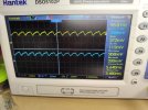
Thanks for the reply. I scoped the speaker terminals with 8 ohm load resistors across the speaker outputs.
It looks like +ve ripple, same on left and right channel. Not affected by volume.
See photo.
I checked the 4 large T03 regulator transistors on the power supply (2 x SB683s ans 2 x SD712s ). They measure good with diode junctions BC and BE , no shorts in circuit.
I'll check the other transistors on the board as well. Some of them are JFETs so I'll have to pull them to test with my Atlas tester.
 

Attachments

  • IMG_20240218_202052_1.jpg
    IMG_20240218_202052_1.jpg
    121.7 KB · Views: 8
Check at C2 and 3.
If we can't find that trace we're in trouble.
 
Back
Top Bottom