• The move to the new server is done. There are some software and database maintenance updates in process. This has us passing the hat around to help out. We appreciate any donations. Seriously, even a dollar helps. The payment page may be found here - https://www.audiokarma.org/support.html

Pioneer SA-9800 buz/ hum. I just can't fix.

Yes. Check the +- 68v rails like you checked the terminals.
Hi, got a bit delayed there. I put the scope probes across one of those caps and the same ripple was there, but when I put the other probe on the other cap the associated fuses x2 (800mA) blew.
Blue display went off
They were the right fuses.
I've not got any 800 mA fuses in stock (who has?). I briefly turned the amp on with 1A fuses that I have and it the display came back on.
Do you think 1A fuses will do for now untill I can get some 800mA?
What do you think think went wrong?
 
You probably accidentally shorted to ground. Lower value fuses, like 3/4 amp would be preferred, especially since things like slipped probes and mistaken leads are pretty common. Caution is the name of the game here.

I still am unsure if the hum is still heard if the preamp and main amp are separated. Did I miss that?
 
Must admit I don't know the amp internals, 250mV ripple on the unregulated supply does not sound unreasonable but in any case we should be using the scope to track it down.

Check ripple at C2 and C3, ie, pins 13 then pin 15 (+/-68Vdc schematic is a bit unclear)
Check output of regulators, pins 3,5,10,2

Check ripple on unregulated supply(rectifier assembly board?) at pins 13,14,17, 8(alt 15)

Check for balance between L&R channels for unregulated supply and for +/-rails in reg supply.
 
Thanks for all your help guys. Lots to go at there.
Things are on hold for a few days as when I scoped C2 and C3, the two 800 mA fuses blew. Not sure if it was a coincidenc or not because the leads were attached when I turned the unit on and I didn't slip with the probes.
I replaced the fuses and turned on without the probes then "pop" ad smoke. Two TO 92 transistors exploded and on testing 3 others had gone bad (5 in total of various TO92s).
Unfortunately the two SK34s JFETs are toast as well
I've replaced 3 of the transistors with equivalent KSA992 / KSC 1845s as appropriate.
I've ordered 2SK34s that are supposed to be NOS originals...let's see.
On further inspection it appears that 5 capacitors on the power board were re-capped with the wrong capacitors before I got the amp. The two 220uF caps ( C2 and C3) were replaced with 470uF (mentioned earlier), the two 2.2 uF caps were mistakenly replaced with 22uF. Also the 10uF cap should be 80v, but was only 50 V.
I'll replace them with the correct values. I wonder if this may be part of the problem as the owner told me that the hum started after he had the power supply board re-capped. Then that strange choking modification was done to resolve the hum by the same tech.
I have also noticed that 3 of the 4 15000uF filter caps keep their charge on switching off at 54 V, but one of them loses it's charge straight away. Would this suggest the capacitor is leaky? Could this be causing the hum?
Anyway, I need to fix the power board with the new components when they arrive before I do any more live testing.
 
Use new 1N4004 for the rectifiers
The higher voltage on the caps is okay if not too high.
This is PS board restore probably where you would of been going anyway.
Other thoughts but no time to express them.
 
I have also noticed that 3 of the 4 15000uF filter caps keep their charge on switching off at 54 V, but one of them loses it's charge straight away. Would this suggest the capacitor is leaky? Could this be causing the hum?
One cap feeds the display and can be discharged quickly through the Fluoroscan display. Labeled as C1.
 
  • Like
Reactions: mbz
One cap feeds the display and can be discharged quickly through the Fluoroscan display. Labeled as C1.
I still don't know what caused the catastrophic failure on the power supply board. I've fully checked all the PCB tracks, solder joints and connections and components, replaced the transistors with equivalent KSA992s / KSC1845s that I have in stock and am waiting for the bits I don't have including those Sk34 JFETs. They were quite expensive and I don't even know if they are fakes. I'm a bit worried it will all go "pop" again when I switch on with the rebuilt board. I have some sk117 JFETs.
Do you think they would work in this power supply?
I'll use Dim bulb, but this prevents the amp coming out of protection.
 
Last edited:
Brilliant. That's the one that discharges quickly on switch off. I thought they were all for the main amp section. That's s that theory out.
Many thanks.
So after the pop and smoke, I rebuilt the power supply board. I replaced all the BJ transistors, diodes and zeners with appropriate equivalents from another thread on AK, re capped with correct replacements checked all the resistors (all measure ok) and checked the PCB for broken tracks dry joints and continuity between components.
The only thing left to to do is replace those obsolete SK34s. One is completely dead (reads as two zeners diodes) on my Atlas Da75 component tester and the other reads as a voltage regulator sometimes (when cold) and sometimes correctly as an N channel JFET (when I warm it with my fingers), so not healthy.
I got some SK34s from Hong Kong, but they are B band and the original smoked SK34s are D band.

The original D band SK34 vitals (when it is recognised by the component tester) are:
Vgs off. 2.07v
Vgs on 0.41v
Gfs 3.4 mA/v
Idss. 3.58 mA
RDS on 435 ohm

The new SK34s are matched to each other by the seller and measure:
Vgs off 0.86v
Vgs on 0.34v
Gfs 2.9 mA/v
Idss 1.16 mA
Rds 395 ohm

Do you think the the new SK34s will be ok?
Are they worth trying or will that risk another catastrophic failure?

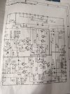
I have looked into using the current limiting diode solution or Echowars current supply circuit with LEDs, but I think they will only work at Q6 source and gate tied together), but not Q5.

Any help would be really appreciated.
 

Attachments

  • IMG_20240228_003548_1.jpg
    IMG_20240228_003548_1.jpg
    121.9 KB · Views: 8
Last edited:
Update.
After rebuilding the power supply board (AWR 196 B - UK HG version with double regulator transistors 2SD712 x 2 and 2SB682 x 2), I replaced the faulty SK34s with GR band SK117 JFETs with Idss 3.5 and 3.6 mA.
Success. All voltages good and no hum. Absolutely quiet noise floor at low and high volume with any input.
I can confirm that the SK117s I used function well on this board and are suitable equivalents for the unobtainium SK34s. (many thanks to TupolevFan on AK for their advice on this)
Surprisingly the SK117s were purchased on ePray and were from China. They are still available and appear to be genuine.
 
Last edited:
Back
Top Bottom