• The move to the new server is done. There are some software and database maintenance updates in process. This has us passing the hat around to help out. We appreciate any donations. Seriously, even a dollar helps. The payment page may be found here - https://www.audiokarma.org/support.html

Pioneer SA-9800 restoration and upgrade

Thank for your insight Mark.

Another thing I forgot to mention is the power meter display. It still seems very dim, not like the one in the 7800, the "aux" indicator especially. I know these fluorescent display tubes get worse with age, but isn't there some way to bring them back? I remember an old Panasonic VCR I had, the channel indicator (7 segment) would be really dim on certain segments. The cure? Set it to channel 88 and leave it on for a few days.

I did think about temporarily re-wiring the display so that all the function indicators (phono, tuner, aux etc) all come on at once, and then leaving it switched on for a couple of days. I wonder, is it possible to to increase the voltage that the display tube gets? I don't mean the heater, but either the screen grids or the anodes?

Lee.
 
<snip.

I wonder, is it possible to to increase the voltage that the display tube gets? I don't mean the heater, but either the screen grids or the anodes?

Lee.
Can of worms, but an increase may not be what is needed.

<snip>
The target is the bright and dim voltages, when the display is cold and working correctly.
Dim IS a higher voltage...

<snip>


several threads have played with the issue, and if i were to address it in toto, i would be typing for a long long time today, about raising voltages, dropping voltages, intermediate voltages, what the OTHER circuits need etc

like i said, a can of worms.

SA-9800 fluorescent display issue

Pioneer SA-9800 fluorescent display failure?
 
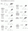
I haven't posted in this thread for over a year, so I figured it was time for an update. I got this amp out of my storage unit a couple of weeks ago, and finally got around to doing some more work on it. Since it has been a while since I worked on this, and since I did one for the SA-7800 I worked on, I made this little chart up that shows what transistors replace the originals. Sure, there is some duplication there, but I can pull a transistor from the board, glance up, and see what it is replaced with and if there is any pin differences to watch for.

SA-9800-14.gif

Here is the second amp board, not quite finished yet. I'm waiting on some resistors to come from Mouser, Mark mentioned before that replacing certain resistors with higher wattage ones was not a good idea, so I have the correct ones on order. I will replace these resistors in the other channel as well. I also need to swap out the two transistors on heatsinks, I have the replacements, just ran out of time today. I know Mark is going to chastise me for pulling the wire wraps off, but I just couldn't work on the board either in the case, or with the outputs flapping around. The situation has changed here at Leesonic's Audio, and most of my work I have to do in a drafty garage on top of my tool box.

SA-9800-15.jpg

Lee.
 
Last edited:
Not chastise...

just observe that desoldering the pins from the board, IF ACCESSIBLE , is a better idea.

You might want to check the bottom of the pins before you heat and pull, sometimes they used a power tool ("planer", saw??) to cut off every thing protruding more than a given distance from the board, and THAT sometimes makes the pin LARGER at the end!!! meaning it will NOT go through the board cleanly - rather it tears at the material. When I can I hit all 4 corners of the end of the pin with a small file to take off the burr, and the pins sail through cleanly with little resistance.

In this specific case, desolder the pins, wiggling them a bit when they cool, to head off solder whisker formation to the foil, which can tear the foil.

That's how I desolder, I wiggle the thing to be removed when I remove the heat so that the remaining solder's surface tension to the pad looses it's connection to the pad as it cools. Then it's easy to straighten the wire without risking the pad (when it's hot).

The pads I loose are just plain time bombs left behind by the last meddler in the unit.
 
No action in this thread since October of last year. I feel bad, this poor old amp has been sitting unloved downstairs for so long. So today, I got it out to see what's what, and what parts I might need to order.

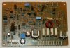
Here is the offending board with the wrong value resistors. As Mark correctly pointed out (and as printed in the service manual), there are certain resistors that should only be replaced with the same type. I thought I was doing good by replacing them with higher wattage ones, but it turns out they are the wattage they are so that they go "poof" when something goes wrong, not the expensive transistors.

SA-9800-16.jpg

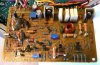
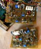
Somewhat weird view of the board, with the correct values installed, shown next to the board for the other channel which I have done previously.

SA-9800-17.jpg

Kind of back together of sorts. I took some time to clean the original mica washers, output transistors and heatsinks of the original dried-up heatsink grease. I then re-installed these with fresh stuff. Yummy!

SA-9800-18.jpg
 
Last edited:
It was raining out today, so I couldn't do any outside projects :grumpy:. Instead, I spent some time cleaning up my Pioneer SA-9800, and setting the bias and offsets. I was able to get the offset at 0mV on the right board, but on the left, it would go no lower than -128mV, this was with the trimmer all the way at it's end stop. What's wrong now? When I hooked up my test speakers to it, the left channel sounded fine at first, but it seemed to get more distorted as the amp warmed up.

I also measured the voltages (again) on the power supply board, referencing Mark's thread here, all the voltages seemed to check out fine. Despite the pictures below, the display is still pretty dim. I have another display board, I will try fitting that and report back.

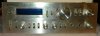
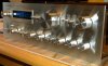
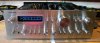
Still, I polished the faceplate and knobs. I can't believe it went from looking like this :

SA-9800-01.jpg

To this :

SA-9800-19.jpg

I'm not sure whether I prefer the side shots with the flash off :

SA-9800-20.jpg

or on :

SA-9800-21.jpg

Off.

SA-9800-22.jpg

On.

SA-9800-23.jpg
 
Last edited:
The offset that didn't adjust, what was the end value of the pot? 0 ohms or full ohms as it was approaching but not reaching 0.000v from -0.200v etc?

Which transistors are original on the board? Resoldered? Q8 and Q12 are going to be the hot ones, and get ksa1220 and ksc2690.

That circuit has a minimum resistance of 62,000 ohms, with the pot taking it from 62,000 ohms to 62,000 + 330,000 ohms...

and the power supply voltages are correct?

Do the 6 way test x 2 for each of the two dual transistors (that's a total of 4x).

To TEST in-situ, either swap q4 and q6 from the other channel, OR sub in ksa992 and ksc1845 individual transistors.


512-KSA992FBU (ln)to-92 ecb 120v .05a .5w 100mhz 300-600hfe $0.17 ea
512-KSC1845FTA (ln)to-92 ecb 120v .05a .5w 100mhz 300-600hfe $0.05 ea


512-KSA1220AYS to-126 ecb 120/a160 1.2a 1.2w/20w 175mhz 35-320hfe $0.39 (R=60-120, O=100/200, Y=160/320)
512-KSC2690AYS to-126 ecb 120/a160 1.2a 1.2w/20w 175mhz 35-320hfe $0.40
 
Last edited:
The offset that didn't adjust, what was the end value of the pot? 0 ohms or full ohms as it was approaching but not reaching 0.000v from -0.200v etc?

Which transistors are original on the board? Resoldered? Q8 and Q12 are going to be the hot ones, and get ksa1220 and ksc2690.

That circuit has a minimum resistance of 62,000 ohms, with the pot taking it from 62,000 ohms to 62,000 + 330,000 ohms...

and the power supply voltages are correct?

Do the 6 way test x 2 for each of the two dual transistors (that's a total of 4x).

To TEST in-situ, either swap q4 and q6 from the other channel, OR sub in ksa992 and ksc1845 individual transistors.

512-KSA992FBU (ln)to-92 ecb 120v .05a .5w 100mhz 300-600hfe $0.17 ea
512-KSC1845FTA (ln)to-92 ecb 120v .05a .5w 100mhz 300-600hfe $0.05 ea

512-KSA1220AYS to-126 ecb 120/a160 1.2a 1.2w/20w 175mhz 35-320hfe $0.39 (R=60-120, O=100/200, Y=160/320)
512-KSC2690AYS to-126 ecb 120/a160 1.2a 1.2w/20w 175mhz 35-320hfe $0.40

The only original transistors on the board are the six legged ones Q3 and Q5. All others have been replaced with your recommendations. Power supply voltages were checked and found to be in order.

Answering your last question first, the pot was all the way to the full ohms side. I checked the value with my meter, and had to pull it off the board just to make sure I wasn't going crazy. The resistance was 194.4k. I then checked the resistance across the two ends of the track, again it was 194.4k. Still didn't believe it, so I checked it with another component tester, the kind you plug the component into and press a button. Same result, 194.4k. This was a Bourns pot, ordered from Mouser, with the order number of 652-3296P-1-204LF which came from another thread. Turns out this is a 200k pot, so perhaps I need something a little higher? The schematic shows a 330k pot.

Lee.
 
try the sub transistors first, OR turn the q3 PNP transistor around to swap sides and see if the offset mirrors to the other polarity.

Or you could remove Q1 and see where the offset goes.
 
Can't belive how good it has shown up after a clean, pity about the fat scratch near the speaker selection know otherwise it looks stunning
 
Wow! I can't believe it's been almost a year since I last posted on this thread. I'm making a concerted effort to get all these unfinished projects out of the way. I've been neglecting them over doing jobs for other people here on AK. That won't stop, just I'm going to make time for my own stuff.

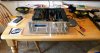
I installed a 500k trimmer the other morning, powered it up, and got the offset adjusted to within specs, actually only a few mV. I ran it for most of the day on those 4 ohm car speakers like all my restorations. I figure, I'd rather it blow up on the bench...(ahem)...kitchen table than sitting in my audio rack. I cranked the trimmers for the power meters up full, so it would read 100w when the reality is much lower. Why? Well, if you've ever seen an old VCR with 7-segment fluorescent display that's been on channel 3 all the time, you'll see the other segments are very dim. If you set it to channel 88 and leave it, sometimes they come back a little. That was the plan with this display. I also grounded pin 10 on the display board, and it got a lot brighter, so there's an issue with the dim/bright switch or wiring I need to address.

I figured I would order the parts to finish recapping the thing, those main power caps sure are expensive, I had to go up a little on the size (uF) and voltage. I was also thinking about replacing the rest of the small signal transistors, and came up with the following substitutions. I wonder if someone (Mark?) could review them and make sure there's nothing wrong.

Q,Q,original part,replacement part
EQ board
1,2,2SC2602,KSC1845
3,4,2SC2602,KSC1845
5,6,2SA1114,KSA992
7,8,2SA1114,KSA992
9,10,2SA726P,KSA992
11,12,2SC1919,KSC1845
13,14,2SC1735,512-KSC2383YTA
15,16,2SA850,512-KSA1013YBU
17,18,2SK131S,unobtanium
19,20,2SC2291,unobtanium
21,22,2SA995,unobtanium
23,24,2SA726P,KSA992
25,26,2SA726P,KSA992
27,28,2SC1919,KSC1845
29,30,2SC1735,512-KSC2383YTA
31,32,2SA850,512-KSA1013YBU

Tone Control
1,2,2SK129A,unobtanium
3,4,2SA798,unobtanium
5,6,2SC1919,KSC1845

I put "unobtainium" for the dual transistors, but I know some of them can be replaced with a matched pair of 992s or 1845. Should I bother changing these, or leaving as is? I know some of the other transistors can get the dreaded "black leg syndrome".

Here are the customary "workbench" pictures...

SA-9800-24.jpg
SA-9800-25.jpg
 
I got the EQ board and the filter board recapped today, and part of the tone control board.

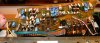
Here are some before and after pictures. I used Nichicon KW series caps, except where they were originally low leakage orange Elnas. If the value was small enough, I used a WIMA film, otherwise I used a Nichicon KL series, bypassed with a WIMA film. I also replaced the trimmers with Bournes items.

SA-9800-26.jpg

SA-9800-27.jpg

SA-9800-28.jpg

SA-9800-29.jpg
 
Last edited:
Got the filter, tone control, protection and display board recapped the other day. Even though they are filters I'll probably never use, I put WIMA film caps in there. I forgot to take "before" pictures of the other boards, the protection board also got three new transistors including a TO126 package device as recommended by Mark the Fixer.

SA-9800-30.jpg
SA-9800-31.jpg
SA-9800-32.jpg
SA-9800-33.jpg
SA-9800-34.jpg
SA-9800-35.jpg
 
Looks good. Now I see a "like" button, should have just used that instead :)
sx-9800 is a nice design, worthy of your efforts and component selections.
I still get a chuckle out of using those to-126 over a to-92L for a saturated switch :-)
 
Last edited:
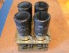
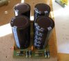
Looking like the four chimneys of Battersea Power Station, here is what Pioneer call the rectifier assembly board, which also features the smoothing caps.

SA-9800-36.jpg

I was able to find some Nippon Chemi-Con caps from Mouser, this is the same brand this amp was originally fitted with. The values were slightly larger, the originals being 15000uF, 71v, 85C, the replacements being 18000uF, 80v and 105C. Despite this, they were the same diameter, and only a little bit shorter. Even better, they were a drop in replacement for the originals, I didn't have to do any modifications. Mouser part number : 661-EKMH800T183MB80T

SA-9800-37.jpg

Here they are fitted to the board, with new 1N5404 diodes as well.

SA-9800-38.jpg

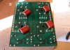
I also added some film bypass caps.

SA-9800-39.jpg
 
Aaaaarrrggghh! :mad:

Can I get a break on this amp? After recapping the tone and filter boards, now there is a very low level hum in the left channel. It goes away when I turn on the high filter. I've tried pulling the pre/power jumpers, it goes away as well, meaning the fault isn't in the power amp stage. I've also tried swapping the wires over from the board with the balance and mode controls where they go to the tone board, the buzz stays in the same channel. Seems to indicate the fault is on the tone or filter board. I hope I haven't damaged one of those ribbon cables that runs between the boards.

Lee.
 
Not sure if this helps Lee, but in rebuilding the SA-8500II, there was a hum when I touched the volume knob. It went away when my finger was removed from the knob. The issue happened to be with a black ground wire that connected the two sections of the volume pot. Must have been acting like an antenna of sorts as giving a touch of solder to the wire wraps didn't help. But moving the wire a little bit did. See if there's a ground wire issue with the filters or from that board.
 
Updated the old, broken picture links. Maybe this will inspire me to get it working 100% finally.

Lee.
 
Back
Top Bottom