

You are using an out of date browser. It may not display this or other websites correctly.
You should upgrade or use an alternative browser.
You should upgrade or use an alternative browser.
Pioneer Spec 1 Transistor Rebuild
- Thread starter PioneerPro
- Start date
-
- Tags
- pioneer spec 1

Those TO-220 package transistors are the same Pinout. They will install the same as the original.
The collector on the TO-220’s is the middle leg and the flange that the mounting screw hole is. This is important to know.
You are on the right track. This hobby has many knowledge paths and each needs to be explored. It’s not a waste to learn and apply your new found skills.
The collector on the TO-220’s is the middle leg and the flange that the mounting screw hole is. This is important to know.
You are on the right track. This hobby has many knowledge paths and each needs to be explored. It’s not a waste to learn and apply your new found skills.
PioneerPro
Active Member
I kind of figured that since they can only attach to the heat sink one way. Good to know but still puts me in a bad place. I might just buy a new used Power Supply Board from Ebay.Those TO-220 package transistors are the same Pinout. They will install the same as the original.
The collector on the TO-220’s is the middle leg and the flange that the mounting screw hole is. This is important to know.
You are on the right track. This hobby has many knowledge paths and each needs to be explored. It’s not a waste to learn and apply your new found skills.
That's not a guarantee.I kind of figured that since they can only attach to the heat sink one way. Good to know but still puts me in a bad place. I might just buy a new used Power Supply Board from Ebay.
Loosen up harnesses to gain what you need for access.
I bet he board has been through a war.
Still. Try to salvage it.
Power Supply Board (AWR-094)
Old list may need equivalents.
AWR-094: C1: 100uF 63v CEA: 647-UPW2A101MHD 100uF 100v
AWR-094: C2: 100uF 63v CEA: 647-UPW2A101MHD 100uF 100v
AWR-094: C5: 220uF 35v CEA: 647-UPW1H221MPD 220uF 50v
AWR-094: C6: 470uF 50v CEA: 647-UPW1J681MHD3 680uF 63v
AWR-094: C7: 470uF 50v CEA: 647-UPW1J681MHD3 680uF 63v
AWR-094: C10: 100uF 50v CEA: 647-UPW2A101MHD 100uF 100v
AWR-094: C11: 220uF 25v CEA: 647-UPW1H221MPD 220uF 50v
AWR-094: C12: 330uF 25v CEA: 647-UPW1V331MPD 330uF 35v
Q1: 2SD313: 863-MJE15032G
Q2: 2SB507: 863-MJE15033G
Q3: 2SC869: 512-KSC2383YTA
Q4: 2SA628: 512-KSA1013YBU
Q5: 2SC945: 512-KSC2383YTA
Q6: 2SA628: 512-KSA1013YBU
Q7: 2SD313: 863-MJE15032G
PioneerPro
Active Member
Yep, those are 100% the exact same parts that I ordered and installed all correctly except for the one KSC2383YTA that I put in backwards them flipped around.That's not a guarantee.
Loosen up harnesses to gain what you need for access.
I bet he board has been through a war.
Still. Try to salvage it.
Power Supply Board (AWR-094)
Old list may need equivalents.
AWR-094: C1: 100uF 63v CEA: 647-UPW2A101MHD 100uF 100v
AWR-094: C2: 100uF 63v CEA: 647-UPW2A101MHD 100uF 100v
AWR-094: C5: 220uF 35v CEA: 647-UPW1H221MPD 220uF 50v
AWR-094: C6: 470uF 50v CEA: 647-UPW1J681MHD3 680uF 63v
AWR-094: C7: 470uF 50v CEA: 647-UPW1J681MHD3 680uF 63v
AWR-094: C10: 100uF 50v CEA: 647-UPW2A101MHD 100uF 100v
AWR-094: C11: 220uF 25v CEA: 647-UPW1H221MPD 220uF 50v
AWR-094: C12: 330uF 25v CEA: 647-UPW1V331MPD 330uF 35v
Q1: 2SD313: 863-MJE15032G
Q2: 2SB507: 863-MJE15033G
Q3: 2SC869: 512-KSC2383YTA
Q4: 2SA628: 512-KSA1013YBU
Q5: 2SC945: 512-KSC2383YTA
Q6: 2SA628: 512-KSA1013YBU
Q7: 2SD313: 863-MJE15032G

Which location was that part put in backwards? It might have contributed to other parts going bad.Yep, those are 100% the exact same parts that I ordered and installed all correctly except for the one KSC2383YTA that I put in backwards them flipped around.
nashou
PioneerPro
Active Member
It was installed in the only place it was supposed to be in. Maybe Q3 but I don't know how to read a schematic. If you look at this photo it is the transistor with the white paint on top of it. I believe it blew the Zenor Diode as discussed earlier and I installed a new diode and started getting voltage readings on pins 1 thru 5 but not the correct voltages. Someone stated that I may of used the wrong voltage Zenor Diode but there are absolutely no numbers on it so I don't know how to tell other than they are totally identical.Which location was that part put in backwards? It might have contributed to other parts going bad.
nashou
Attachments
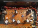
You will have to somehow figure out how to read a schematic for us to help 
But since in an earlier post it was stated that Q3 and Q5 use that KSC2383YTA.
I dont have the schematic but maybe one of the others such as @zebulon1 can point out which one it is.
I'll see if I can down load the schematic, at work so it wont be till I get home.
Athanasios
But since in an earlier post it was stated that Q3 and Q5 use that KSC2383YTA.
I dont have the schematic but maybe one of the others such as @zebulon1 can point out which one it is.
I'll see if I can down load the schematic, at work so it wont be till I get home.
Athanasios

Scott75s1974
Well-Known Member
Glad folks are helping you. A few points of procedure from a fellow very amateur restorer...
0. Do one transistor at a time.
1. Photograph each transistor before you remove it in a way that shows its alignment ...and number if possible.
2. Get one of those cheap component testers. When you remove a transistor keep its pins aligned as they are on board. Put it in the tester. It will give you the pinout. Compare that with the board markings.
3. Check the replacement in the tester. Form the pins on the replacement as needed (it may be a different pinout and different bending regime.
4. solder it in
5. Start it up on a dim bulb tester and see if it's ok.
You can bump that to 2 or 3 transistors at a time. That's a manageable backtrack number to find an error.
Also keep checking the sound.
0. Do one transistor at a time.
1. Photograph each transistor before you remove it in a way that shows its alignment ...and number if possible.
2. Get one of those cheap component testers. When you remove a transistor keep its pins aligned as they are on board. Put it in the tester. It will give you the pinout. Compare that with the board markings.
3. Check the replacement in the tester. Form the pins on the replacement as needed (it may be a different pinout and different bending regime.
4. solder it in
5. Start it up on a dim bulb tester and see if it's ok.
You can bump that to 2 or 3 transistors at a time. That's a manageable backtrack number to find an error.
Also keep checking the sound.

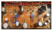
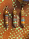
The resistors on the blue box do not pass visual inspection (R5-R6), if they are open you will see full positive rail voltage on pins 1~5. I strongly suggest to be tested with DMM and post the values. IF the OP do not know how, just ask.
If you guys need me to identify the Emitter, collector/ base on the board just ask.
Source:
Page 33 service manual and post #7

Scott75s1974
Well-Known Member
Just want to note that the diagram "foil side" means looking from the bottom.
PioneerPro
Active Member
View attachment 3703739
The resistors on the blue box do not pass visual inspection (R5-R6), if they are open you will see full positive rail voltage on pins 1~5. I strongly suggest to be tested with DMM and post the values. IF the OP do not know how, just ask.
If you guys need me to identify the Emitter, collector/ base on the board just ask.
Source:
Page 33 service manual and post #7
HIPOCRATES
OK SO YES I WAS CORRECT IT WAS Q3 THAT NEEDED TO BE FLIPPED AFTER BEING INSTALLED WRONG.
I will double checked the resistors and here is what I found in the order I have them marked in the picture below. Using a standard Ohm meter and left in circuit.
1 - 2.78
2 - 7.98
3 - 2.65
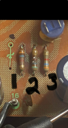
I am 100% good on the ECB's and BCE;s. That's how I figured out which ones I originally installed wrong.
The usually go open... and measure on legs with the Ω setting1 - 2.78
2 - 7.98
3 - 2.65

This should be the values. more that 5% off of the nominal values and they are done and should be replaced, but to be honest, to have a resistor looking like those on the left is not acceptable, specially on a very nice preamp power supply. IMO

Last edited:
PioneerPro
Active Member
The usually go open... and measure on legs with the Ω setting
View attachment 3703831
This should be the values.
OK, they shall be then. Going to replace the Zener Diodes and the Q3 Transistor I put in backwards as well. I might even replace some of my friends while I am at it.
Is there anything else you would recommend I replace?
Thanks for all your help
Attachments


Only those resistors, they are critical. IF D1(24V Zener) and all the transistors are correctly installed. That board should work.Is there anything else you would recommend I replace?
PioneerPro
Active Member
Can someone give me the 100% correct PINOUT of the 2SC945 Transistor. These are old and no longer produced and I have researched on line and found confliction data because AI is stupid.
Thank You
Thank You
Emitter-Collector-Base2SC945 Transistor
Here is the data sheetCan someone give me the 100% correct PINOUT of the 2SC945 Transistor. These are old and no longer produced and I have researched on line and found confliction data because AI is stupid.
Thank You
Attachments
PioneerPro
Active Member
Well, I had to flip 2 more around for the second time on the Mixing Amp Board. Yes I know, that's not its actual name but I've had one hell of a day.Emitter-Collector-Base
New transistors and Z diodes and resisters ordered.
Scott75s1974
Well-Known Member
If I can re-up my suggestion in #29 above to get yourself one of these cheap component testers. They give you pinout of what you are removing (as long as it's not blown). So you don't need to guess or search the AI-poisoned internet or wait for true knowledge from AK experts for pinouts. I spent $16 on this one because it had a plastic case. If I had to do it again, I'd splurge $29 on this one for the attachments. These aren't pro tools like the Peaks. They are just to give you a quick check of components coming out and going in. Really essential for beginners.
