• The move to the new server is done. There are some software and database maintenance updates in process. This has us passing the hat around to help out. We appreciate any donations. Seriously, even a dollar helps. The payment page may be found here - https://www.audiokarma.org/support.html

Pioneer Spec 1 Transistor Rebuild

PioneerPro

Active Member
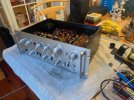
I have a Pioneer Spec 1 Preamp that I did a recap on about 4 years ago. I bought the recap kit off Ebay and did the work myself. Everything was working just fine but there was a very very slight hum and a pop when I would turn the Source switch. I read up on this and found that there were a lot of transistors that go bad and so I decided to finish the job I started and do a retransistor job on the preamp.

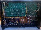
I follow this thread Pioneer Spec 1 Question and at the bottom of page 2 there was a transistor BOM list that I copied and ordered thru Mouser. I ordered the 50 Transistors listed and replaced all the basic black transistors including the 3 output transistors on the Power Board. I did not change the small Relay that is located on the Mixing Amp Board. I did however take that relay cover off and tried to clean the contacts with some 1000 grit sandpaper but the contacts were very difficult to access so I did nothing and put the cover back on.

I plugged the Preamp back into my stereo system and there is no sound. The power light did not come on but then illuminated 10 seconds later. The power light above the power switch lights up as soon as I turn the preamp on but I hear no click. I hear and feel and see nothing happening with the relay on the Mixing Amp board but the two larger relays located under the Power Supply board are working just fine both engaging and disengaging when I operate the Speaker A & B switch.

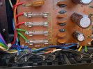
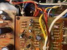
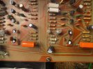
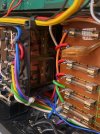
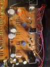
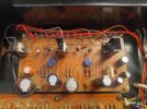
I took the Spec 1 back to the bench and went thru the BOM list and found that I had 17 Transistors that were installed incorrectly. For example the KSA992 transistors with a ECB Pinout that replaced the 2SA726 transistors with a BCE Pinout have the opposite PINOUT and so they all needed to be removed and flipped 180 degrees facing the opposite way of what they were. I looked up all the Pinouts on the new transistors in the Mouser Datasheets and so I know they are correct. I looked up all the Pinouts on the old transistors and got various answers thru Google so I gave up on that and went into Audiokarma and did a search on all the old transistor Pinouts and believe I got the correct info. I flipped all 17 transistors marked with white paint in the pictures around that I feel were incorrectly installed and thought I would be good now. I once again have no sound. I checked and double checked everything, every setting, every input every cable every source and every speaker wire and still have no sound.

I have a lot of electronics repair knowledge and have worked on a lot of different components and fixed a lot of stuff but I have no formal training. I can fix any mechanical mechanism on any cassette 8 track Reel to Reel and turntable but when it comes to electronics I struggle. Any advice and help would be appreciated.

Thank you
 

Attachments

  • 7e7dacc0-865c-4f6f-b578-160e041ebab1.jpg
    7e7dacc0-865c-4f6f-b578-160e041ebab1.jpg
    127.4 KB · Views: 23
  • 9d0d2a83-f099-424b-89e5-f1f0a93fd357.jpg
    9d0d2a83-f099-424b-89e5-f1f0a93fd357.jpg
    139.8 KB · Views: 25
  • 15b2037d-41be-4620-bf6f-e895bca77159.jpg
    15b2037d-41be-4620-bf6f-e895bca77159.jpg
    131.6 KB · Views: 22
  • 30fb1035-fbb3-4aea-a2af-f9a3f110e1a8.jpg
    30fb1035-fbb3-4aea-a2af-f9a3f110e1a8.jpg
    147.2 KB · Views: 23
  • 56c0aea1-ca6d-44fe-a9c5-545dea790c1a.jpg
    56c0aea1-ca6d-44fe-a9c5-545dea790c1a.jpg
    170.8 KB · Views: 24
  • 4e895233-8d36-4c16-ac2d-e3c4cd660835.jpg
    4e895233-8d36-4c16-ac2d-e3c4cd660835.jpg
    129.5 KB · Views: 24
  • 6a1abb0d-7a1d-4994-a374-2ea2e70ce783.jpg
    6a1abb0d-7a1d-4994-a374-2ea2e70ce783.jpg
    78.6 KB · Views: 23
  • 0a67a7d9-377a-43a2-98ea-0bfad7d6a56b.jpg
    0a67a7d9-377a-43a2-98ea-0bfad7d6a56b.jpg
    146.5 KB · Views: 24
Register to hide this ad
Here is a list of all the old transistors and their replacements and the ones that had reverse Pinouts according to what I found.

I also tested the voltage readings on the Power Supply board, they are as follows.

Pins 1 thru 5 = 1 volt
Pin 6 = 71 volt
Pin 7 = -71 volts
Pin 8 = 53 volts
Pin 9 = -53 volts
Pin 10 = blank
Pin 11 and 12 Negative 53 volts
Pin 13 = 36 volts
Pin 14 and 15 = 24 volts
 

Attachments

  • 7ebbb882-a686-4827-8eaa-046a2c2dac9b.jpg
    7ebbb882-a686-4827-8eaa-046a2c2dac9b.jpg
    99 KB · Views: 10
1./ Don't go replacing stuff just because someone on the internet says so, is a terrible habit... discard opinions saying you have to replace this and that, they don't know what is the problem you have, and chances are that you will get in worst trouble.

2./ Same goes with following lists, at least isolate the board with problems.

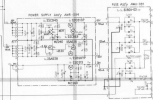
3./ Be very specific and concise, if you are talking about the regulated power supply (AWR-094) state it, according with the schematic those voltages are wrong, go back and check your work and wiring and C6,C7 should be 63V, and those zeners.

1771364509575.png
4./ Diagnostic first, then recap or whatever you want to do with your unit later
5./ Always work one board at the time and test after you finish it.
 
Well this is Audiokarma and if you can't get good advice here, I don't know where you can. I replaced all the transistors because I knew some needed to be replaced and what would it hurt to replace the other old ones and start with a clean slate and a new better Preamp than what I had. Once again I have no formal training in electronics repair s I do not know how to diagnose, I am basically a parts installer like most mechanics these day. There was no reason to diagnose because there was nothing wrong with the preamp but being 50 years old you would assume it needs a recap. When I rebuilt my SX-950 I did one board at a time and checked the unit for sound, but with this Preamp it would take a lot of work to hook up a source, an amp and speakers every time you rebuilt one of the 5 boards. I had the schematic that you provided I am just not good at reading it. I see the transistors and the voltages but after that I am lost.
 
Stop the banter.
We’ll keep this thread.
By the way you posted in the DYI and not the Pioneer forum.
The positive rail is missing from the power supply.
Probably the one BJT that was backwards?
“Hiopcrates” screen shot the PS for you. Pins 1-4 need to have that 48+ volts DC.
Check or replace zener diode D1, 24v (.5w) and check all three of those transistors in that positive rail circuit.
 
Well this is Audiokarma and if you can't get good advice here, I don't know where you can. I replaced all the transistors because I knew some needed to be replaced and what would it hurt to replace the other old ones and start with a clean slate and a new better Preamp than what I had. Once again I have no formal training in electronics repair s I do not know how to diagnose, I am basically a parts installer like most mechanics these day. There was no reason to diagnose because there was nothing wrong with the preamp but being 50 years old you would assume it needs a recap. When I rebuilt my SX-950 I did one board at a time and checked the unit for sound, but with this Preamp it would take a lot of work to hook up a source, an amp and speakers every time you rebuilt one of the 5 boards. I had the schematic that you provided I am just not good at reading it. I see the transistors and the voltages but after that I am lost.
So you installed a bunch of stuff incorrectly and you can't read a schematic? We can give advice, but it's useless if you can't act on it correctly.
Check all your work, again, and I hope you didn't reuse any transistors you put in wrong. Then check power supply outputs as shown in the picture above.

Or - and maybe this is best - bring it to a tech.
 
zebulon1

Sorry, I looked at the Pioneer Forum and saw no repair threads there so I thought this repair forum would be better.

Yes pins 1 thru 4 are all dead, showing only 1 volt. I did turn the one BJT around but assume the damage had already been done.

The two Zenor diodes in this board are giving me different resistance values so I assume one is bad. I have some Zenor diodes on hand, do they all have the same values?

What about the resistor in the attached photo?

Should I delete this thread and redo it in the Pioneer Forum?
 

Attachments

  • dbcbcb05-1976-435f-98ff-0f5c58a8a5ca.jpg
    dbcbcb05-1976-435f-98ff-0f5c58a8a5ca.jpg
    130.4 KB · Views: 13
  • 5701d188-f279-4b87-b53e-bef45928b411.jpg
    5701d188-f279-4b87-b53e-bef45928b411.jpg
    127 KB · Views: 13
So you installed a bunch of stuff incorrectly and you can't read a schematic? We can give advice, but it's useless if you can't act on it correctly.
Check all your work, again, and I hope you didn't reuse any transistors you put in wrong. Then check power supply outputs as shown in the picture above.

Or - and maybe this is best - bring it to a tech.
Ivandezande

I only installed a few transistors backwards because I could not find the correct PINOUT info I needed and assumed since the transistors came from a BOM from Audiokarma that they were all correct, I will not make this mistake twice,
 
You should have a diode check function on your meter. It will read the forward voltage across the diode. Using the ohm function will show continuity across one side and "OL" (Overload) with the meter leads flopped over the reverse polarity on the diode leads. Search Google for the diode test with a meter and the understanding of its function.
You can test the diodes in circuit with confidence.
Check the resistor for value but it looks okay. Crusty for sure but it should be checked. Check any component you question. Always follow your gut instinct.
Keep the thread here.
 
Last edited:
zebulon1

Yes I have a diode function and tested and replaced the Zenor on the left side of the Power Supply board.

I removed the Zenor diode and installed a new one. I now have voltages on pins 1 thru 5, they are as follows.

1 65v
2 65v
3 65v
4 65v
5 65v
6 67v
7 -70v
8 10v
9 10v
10 NA
11 10v
12 10v
13 36v
14 25v
15 25v

Preamp is still not working with no sound but obviously Pins 8 thru 12 are way off. The middle Output transistor Q2 (2SB507P) is now warm but maybe warmer than it should be since the Preamp was only for less than 30 seconds to get the voltage readings.

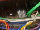
Can you tell me what the relay in my picture #3 in my original post is and how to test it? I have not heard it click at all.
 
Last edited:
Ivandezande

I only installed a few transistors backwards because I could not find the correct PINOUT info I needed and assumed since the transistors came from a BOM from Audiokarma that they were all correct, I will not make this mistake twice,
You couldn't find the KSA992 datasheet and compare it to the symbol on the board?
 
zebulon1

Yes I have a diode function and tested and replaced the Zenor on the left side of the Power Supply board.

I removed the Zenor diode and installed a new one. I now have voltages on pins 1 thru 5, they are as follows.

1 65v
2 65v
3 65v
4 65v
5 65v
6 67v
7 -70v
8 10v
9 10v
10 NA
11 10v
12 10v
13 36v
14 25v
15 25v

Preamp is still not working with no sound but obviously Pins 8 thru 12 are way off. The middle Output transistor Q2 (2SB507P) is now warm but maybe warmer than it should be since the Preamp was only for less than 30 seconds to get the voltage readings.

Can you tell me what the replay in my picture #3 in my original post is and how to test it? I have not heard it click at all.
The relay is for mic input. It will not turn on unless you plug something into the mic jack. You can see this in the schematic.
 
Pins 6, 7 and 13 are read in ACv.
The rest of the pins are read in DCv.
You may of installed the wrong zener diode in D1? It should be a 24v zener diode. Pins 1-5 should read +48 volts.
Pins 8-12 should be the negative rail and read -48 volts. Something is wrong in that circuit. It was working on your last post.
Pins 14 and 15 are working perfectly.
Power up using your DBT with a 40 watt bulb.
 
Pins 6, 7 and 13 are read in ACv.
Not quite
Pin 6 is the positive rail, Pin 7 is the negative rails, both comes from it comes from AWX-091, Pin 13 is 32V... All of the are recitifed and in DC
1771440923537.png
OP:
AWR-094 is a linear regulated power supply, unless you get the pinouts well and test those 3.6K and 5.6k cracked resistors, You gonna blow something.
That 24V Zener sets the reference voltage on the positive rail, is fed by positive rail thru 5.6K cracked resistor, have a parallel 220uf capacitor for filtering and it drives q5 that we don't know if is even with the correctly installed, is a very loaded node and you can't dmm that thing and expect good results.

Same goes with the negative rail.

Q7 is fine. (regulated, capacitance multiplier section).

Unless you get the pinouts fine, check for burned components, the voltages are going to be a mess.
 
You couldn't find the KSA992 datasheet and compare it to the symbol on the board?
Yes I found the datasheet for that just fine I however was unable to find a reliable source to give me the Pinout for the 2SA726 and the 2SC1313 and the 2SC869 that the new transistors replaced because they were very old and discontinued.
 
Yes I found the datasheet for that just fine I however was unable to find a reliable source to give me the Pinout for the 2SA726 and the 2SC1313 and the 2SC869 that the new transistors replaced because they were very old and discontinued.
Forget it, what is done is done.

This AWR-094 board grabs the rectified current from AWX-091 board on PIN 6 (positive) PIN 7 (negative) and PIN13 (positive). PIN 16 is common or ground.
Then it regulate it for the rest of the unit and give +48V on pins 1~5 and -48V on pins 8-12.

If you do not get your pinouts well your will blow stuff.

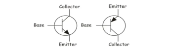
Your board will have some marks with a transistor symbol... Be SURE that your transistors pinout matches.

1771442315809.png

The one on the left is NPN the other PNP
 
Last edited:
The board has the transistor symbols. You can match those to the modern BJT data sheets.
The originals still can be found, it takes some research.
2SC1313
 
So you installed a bunch of stuff incorrectly and you can't read a schematic? We can give advice, but it's useless if you can't act on it correctly.
Check all your work, again, and I hope you didn't reuse any transistors you put in wrong. Then check power supply outputs as shown in the picture above.

Or - and maybe this is best - bring it to a tech.
Yes I did reuse all the transistors that I got wrong. I took them out flipped then 180 degrees and put them back in. It sounds like I have some new ordering to do.

Sorry buddy, no techs in Iowa, that is why I am doing the work myself. Des Moines Iowa area.
 
No worries.
Quote me from a post or mention me in this thread. That will alert me to check in.
 
No worries.
Quote me from a post or mention me in this thread. That will alert me to check in.
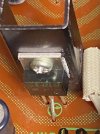
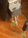
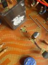
I think I may of figured out the problem. There are 3 output transistors on the AWR-094 Board

The original ones on the ends were 2SD313P's and the one in the middle is a 2SB507P

According to what I found on line, doing way too much research than need be is as follows.

The 2sd313P is a NPN trans with a BCE Pinout being replaced with a MJE15032G transistor with a BCE Pinout and so these two are good. The arrow in the circle drawing on the board points to the last leg of the transistor for the Emitter, Right???

The old transistor in the middle was a 2SB507P with a BCE pinout and it is a PNP. It is replaced by a MJE15033G transistor with a BCE also so it should be good, however the drawing on the board (the circle with the arrow) points to the first leg of the transistor which is the Base and not the Emitter. I thought the arrow points to the Emitter only???

So either Pioneer got the schematics drawing on the board wrong or I have the wrong info for the 2SB507P transistor and the MJE15033G is not going to work here.
 

Attachments

  • c82d5dfa-78f3-4c73-8649-b63027882093.jpg
    c82d5dfa-78f3-4c73-8649-b63027882093.jpg
    123 KB · Views: 10
  • 20e2fe99-4f01-4729-9fd1-3396f7b326fa.jpg
    20e2fe99-4f01-4729-9fd1-3396f7b326fa.jpg
    103.1 KB · Views: 12
  • 986c798e-7dff-49fa-a35e-855482eee231.jpg
    986c798e-7dff-49fa-a35e-855482eee231.jpg
    94.3 KB · Views: 11
  • d1f816fe-c115-46fc-ab3e-7b10975a5bf2.jpg
    d1f816fe-c115-46fc-ab3e-7b10975a5bf2.jpg
    136.3 KB · Views: 9
  • 1e41f81c-8c6a-4dcd-87cb-9675136ed34e.jpg
    1e41f81c-8c6a-4dcd-87cb-9675136ed34e.jpg
    132 KB · Views: 9
Last edited:
Back
Top Bottom