• The move to the new server is done. There are some software and database maintenance updates in process. This has us passing the hat around to help out. We appreciate any donations. Seriously, even a dollar helps. The payment page may be found here - https://www.audiokarma.org/support.html

Pioneer SPEC-2 recap and restoration thread!

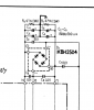
There are a total of (6) 512-KSC1845FTA needed for the Meter Amp Board (AWM-081) that are listed under parts for that board, but missing in the final BOM.

The documentation and photos for this Spec-2 restoration is exceptional work, and it's helping me immensely.
 
I see your bias sitting right at 30mV.

Mine changes a lot with the heat of the AMP. they will be around 4mV when I turn it on then after 30 minutes it will be at 30mV but it depends on the temp, if the unit gets hotter the bias mV will be higher. I am just wondering if that is normal.
 
I have done the 4 main Caps and the relays on the Power Amp boards. I have humming on both speakers when i turn it up, do you know what that would be from. this is a big parts list. I always grew up thinking if it ant brock don’t fix it. so of all those parts what would you be most likely to do?
 
I have done the 4 main Caps and the relays on the Power Amp boards. I have humming on both speakers when i turn it up, do you know what that would be from. this is a big parts list. I always grew up thinking if it ant brock don’t fix it. so of all those parts what would you be most likely to do?
All of them. It IS broke.
 
I see your bias sitting right at 30mV.

Mine changes a lot with the heat of the AMP. they will be around 4mV when I turn it on then after 30 minutes it will be at 30mV but it depends on the temp, if the unit gets hotter the bias mV will be higher. I am just wondering if that is normal.
Idle current.
 
yes its idle curent. knobs set to 0 no imput. like I said when I turn it on (cold) bias is 4mV, then after it warms up, 30 minutes it will be at 30mV
I meant to say idle current will change with the heat of the amp. Again, pay close attention to what mtf is telling you. Just a suggestion. You are in another thread that is intended to be a rebuild of a Spec-2. Not intended to solve your idle current (or bias if you will. I try to stay consistent) and trim pot issue. Stay with your own thread or the water might get muddy. Mattsd’s thread is excellent for reference on a rebuild. Just suggesting. Not trying to be critical. I’m not qualified to be a critic.
 
If it wasn't for this post, (Thanks Matt!!) I wouldn't have known that SPEC-2 I just opened up does not have the series of resistors and caps wired between the Filter cap and the terminal block as shown in Matts photo.
Wx1mZN3.jpg

Can someone tell me the values so that I can add them back in? I assume they are supposed to be there for a reason?
 
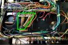
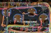
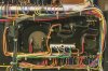
It only has them on 2, they are not on the other 2 by default. - see pictures.

I dont know the values.
 

Attachments

  • SPEC-2 New CAPS.jpg
    SPEC-2 New CAPS.jpg
    148.6 KB · Views: 55
  • SPEC-2 Old CAPS.jpg
    SPEC-2 Old CAPS.jpg
    148.5 KB · Views: 54
theory:
power wastage, so avoided bleeders on early production BUT
they changed that after too many problems were caused by the huge charge hanging around?

i.e. it cost them more money to leave them out and fix the problems they caused.
 
I guess I'm pretty late to the party... I've got a SPEC 2 in early 2020, didn't have much chance to use it, as it appears to be broken (but thankfully untouched by anyone AFAIK). The speaker relay doesn't seem to activate, also I really don't like the old and tired lamp cord it have for power. I was wondering if it would be viable to just have a new custom back panel made, and have it cut to accept modern parts and IEC power inlet. The panel appears to be completely flat, so all that's needed would be a sheet metal (or even heavy duty PCB) with pre-cut holes.

Anything thinking of replacing the back panel as well? Mine back panel is in great shape, just couldn't bear to cut into the original sheet metal...
 
Back
Top Bottom