• The move to the new server is done. There are some software and database maintenance updates in process. This has us passing the hat around to help out. We appreciate any donations. Seriously, even a dollar helps. The payment page may be found here - https://www.audiokarma.org/support.html

Pioneer SX-1010 no sound

I have 4 extra 512-1n4004. If theoe are suitable I can use them, with some guidance as to the best way to hook them up.

I will also dig up the 2 threads I found mentioning the bridge rectifier replacement. Believe they are used in a Yamaha receiver as well, and someone was going to replace with Freds.
 
Heat sinking and physical characteristics are pretty important for the final fix. I'm not sure of the fred case type that was used.

Yes, the 1n4004s can be used, with two jumpers, to connect the d1 cathodes together(pin 16) and the d2 anodes together(pin 15),which are normally connected by the mounting strap.

Ever since my last post (7:30) I have been working on finding appropriate rectifiers. Looks like about 5 bucks apiece, with stud mount devices.

Thanks for looking into the replacement rectifiers. I am not seeing the above layout in my head. Where do pins 1 and 2 come into play? Can you spell out the 1n4004 connections a little more for me?
 
Thanks for looking into the replacement rectifiers. I am not seeing the above layout in my head. Where do pins 1 and 2 come into play? Can you spell out the 1n4004 connections a little more for me?

PM me an email address. What I send back, you can post. But imagine how huge my attachment space would be (and is, even so) with all these threads.

The pins 1 & 2 wiring is an input, and can stand alone. The other output wiring has the gap to be jumped.

edit PM received, email sent.
 
Last edited:
Major progress!

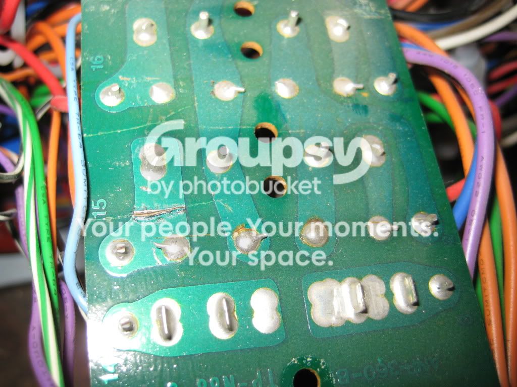
So MTF sent me the info on rebuilding the bridge rectifiers and look what I found after pulling the board

IMG_4415.jpg


So, a few hits of solder later and we have relay engagement and audio! I have not powered it up off the dim bulb yet though.

Not sure we're all the way there yet. But, I wanted to thank MTF for all his patience and TIME spent helping me fumble through this process.

So, a few questions now:
1. Is there a better fix than solder along the broken line?

2. Is the next step bringing it up on full line level and setting bias and offset? Do I need to use the 8 ohm resistor?

3. What is the best thing to adhere the plastic insides of the knobs and swiches to the aluminum ousides?

I am sure there will be a ton more questions as I start recapping the rest, adding the extra diode, etc, etc....
 
Last edited:
I would strip some hookup wire and solder it across those cracks. I'd also do this on the areas that are not cracked all the way across. See what ideas Mark has as well.

Nice job!!
 
So, I was pretty close. Glad it's not the transformer and the hard to find rectifier. :thmbsp: But it looks deliberate. Once MTF okays, enjoy.:music:
 
I set the bias and offset and have been rocking this thing today. Sound is crisp.

There is a very slight hum/buzz on both channels at high volume with the source paused. It is worse without my iPod plugged in to Aux input. No change when flipping the wall plug. Not at all noticeable when music is playing. Maybe this is somewhat normal at higher volumes.

Also get some slight static moving the tuning knob when in Aux.

I also need a bottom cover if anyone has any ideas.
 
Bottom cover. Take your measurements of the actual case. go to a sheet metal shop and ask them to cut a piece of 0.080 aluminum. Get it home, and mark your screw holes, and about 50-60 1/4" holes for ventilation. space them so there is 1/8" between holes.

Get some appliance feet at ace hardware.

And you're good to go.

Larry

Aluminum as opposed to steel? Wouldn't it crunch when he decides to stack them? Just curious.:scratch2:
 
I normally don't stack equipment, except on individual shelves. Steel is ok. IIRC there is a center strut in the 1010 so I don't think it would go crunch. It might give a bit more than steel.
 
To address the buzz I am going to re-cap the power supply board along with all new transistors. Also going to address the protection board. Will post results.
 
To address the buzz, you'd best be talking to me, instead of flailing in the dark.....

You probably have good raw dc now on the caps, BUT we really needed to see DC and AC(blocked dc) measurements on the two big caps. The cut foil completely isolated pin 15 which fed the minus side capacitor, but we haven't proved that all 4 of the old rectifiers are ok. One being out would buzz.

Pull the pre-out / amp in jumpers and crank it up, listening for the buzz. At least that will exonerate the preamp section.

Shorting plugs for the amp in plugs would be a good idea for a stringent test.

Then we would need to measure the AC(blocked dc) voltages present upon your regulated DC voltages that feed the amp / preamp etc...

To go it blindly, in the power supply, you need to do the caps, transistors AND rectifiers (1n4004's will be fine ).

Realistically, the AC voltage with DC blocking cap test on pins 1 to 2 of the fuse board should read just about the same with or without the cap.

Just to be sure (not insulting):
pin 2 > black meter lead
pin 1 > one side of blocking cap, other side of blocking cap to red meter lead.
& good electrical conductivity all round.
 
Buzz is definitely coming from white wire on the main relay. Moving the white wire makes it stop. I believe it may be broken somewhere between the speaker switch board and the relay.

Suggestions?
 
Last edited:
Replace the relay driver transistor. It may be weak, and barely pulling the relay in. It is the second half of the situation, the first half was the transistor replacement in the power supply.

Use the same type as you did in the power supply, for Q7.
or do all the vulnerable parts.

awm062 board parts (for completeness)

Q1-Q2 2SC869-C
512-KSC1845EBU (ln)to-92 ecb 120v .05a .5w 100mhz 150-800hfe $0.05 ea

Q3, Q4 SSC945-Q
512-KSC945CLTA to-92 eCb 50v .15a .25w 300mhz 40-700hfe $0.05 ea

Q5 2SA733-Q
512-KSA733CLTA to-92 eCb 50v .15a .25w 180mhz 40-700hfe $0.05 ea

*** for the 733C and 945C , the C means ecb lead layout instead of ebc.


These are the parts you should get:

Q6 SSC945-Q
512-KSD1616ALBU to-92 ecb 60v 1a 0.75w 160mhz 135-400hfe $0.09

Q7 2SC1384-R
512-KSC2690AYS to-126 ecb 120/a160v 1.2a 20w 155mhz 35-320hfe $0.40

C1, C2 0.22uf
598-DSF050J224 CDE Metallized Polypropylene Film Capacitors 0.22uF 50V 5% $0.14

C3, C4 330uf 6v 647-UPW1A331MPD 330uf 10v $0.20 ea

C5 4.7uf 25v 647-UPW1H4R7MDD 4.7uf 50v $0.12

C6 100uf 16v 647-UPW1H101MPD 100uf 50v $0.22

Also add a 1n4004 flyback diode to pins 9 (anode) and 10(cathode, banded end) on the board.

512-1n4004 conventional rectifier 1a 400v $0.06 ea
 
Last edited:
Replaced the transistors and caps on the protection board and added the diode. You had me get all these parts on the first order. Turned it on and relay wouldn't engage. Went to check bias and offset and accidentally bridged two pins on the amp board. There was a groan from the transformer and it went dead. It blew the power switch fuse. Not sure what else damage was done. Will get a new fuse tomorrow and bring it back up on DBT:thumbsdn:
 
Last edited:
Not good, main fuse = output transistors.

I would have had you measuring voltages at the protection board to find out what's up... The output voltages of the amp are available on pins 1 & 3.
 
Not good, main fuse = output transistors.

I would have had you measuring voltages at the protection board to find out what's up... The output voltages of the amp are available on pins 1 & 3.

I was working tired, it was stupid. I believe I hit pins 14 and 12 with my multimeter on the right channel instead of 14 and 16.

Going to replace the 6.25a slo-blo fuse and check the rest of them.

If there are 2 npn and 2 pnp output transistors that test good, is it a good idea to try and bring it up on dim bulb with the other sockets insulated?

Back to page 1...
 
Last edited:
NO power. Check all the output transistors in-situ for collector to emitter shorts.

Actually thinking about it, we are a LONG ways from applying power again.

Look for other blown transistors as well in that channel - the out of circuit tests IF the in circuit test doesn't reveal a short straight off...

It may save you replacing more types of parts - like resistors etc....

Be careful of that bias diode connected between the amp board and the heat sink - those little wires LOVE to break off flush at the component's body...
Tuck them somewhere safe...

One of the npn output transistors is shorted on the right channel. The rest test fine. Q9 and Q10 are toast as well. All others test fine.
 
Back
Top Bottom